LIGHTING SYSTEM Turn Signal Switch Circuit
DESCRIPTION
The combination meter receives the turn signal switch information and controls the turn signal lights.
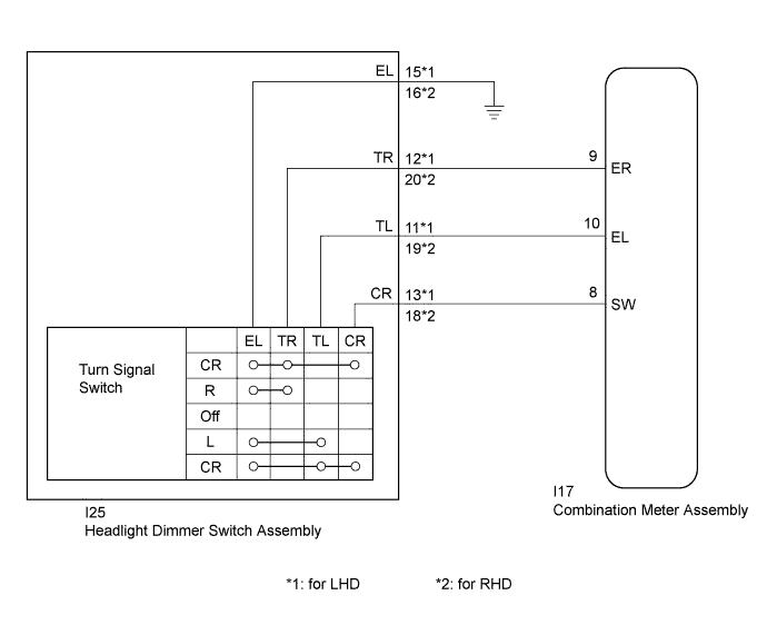
WIRING DIAGRAM
INSPECTION PROCEDURE
PROCEDURE
-
READ VALUE USING INTELLIGENT TESTER
-
Connect the intelligent tester to the DLC3.
-
Turn the ignition switch to ON.
-
Turn the intelligent tester on.
-
Enter the following menus: Body / Combination Meter / Data List.
-
Read the Data List according to the display on the intelligent tester.
Combination Meter Tester Display Measurement Item/Range Normal Condition Diagnostic Note Turn Signal Switch (Right) Turn signal switch (right) signal/ON or OFF ON: Turn signal switch (right) on
OFF: Turn signal switch (right) off
- Turn Signal Switch (Left) Turn signal switch (left) signal/ON or OFF ON: Turn signal switch (left) on
OFF: Turn signal switch (left) off
- Turn Switch Signal (Full Turn) Turn signal switch (full turn) signal/ON or OFF ON: Turn signal switch (left or right) on
OFF: Turn signal switch (left and right) off
- OK Normal conditions listed above are displayed.
NG 
INSPECT HEADLIGHT DIMMER SWITCH ASSEMBLY Click here
OK 
PROCEED TO NEXT SUSPECTED AREA SHOWN IN PROBLEM SYMPTOMS TABLE Click here
-
-
INSPECT HEADLIGHT DIMMER SWITCH ASSEMBLY
-
Remove the headlight dimmer switch assembly (for TMC, TMMR Made: Click here, (for TMMK Made: Click here.
-
for LHD:
-
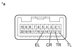
Text in Illustration *a Component without harness connected
(Headlight Dimmer Switch Assembly)
Measure the resistance according to the value(s) in the table below.
Standard Resistance Tester Connection Condition Specified Condition 12 (TR) - 15 (EL) Turn signal switch in neutral position 10 kΩ or higher 11 (TL) - 15 (EL) Turn signal switch in neutral position 10 kΩ or higher 13 (CR) - 15 (EL) Turn signal switch in neutral position 10 kΩ or higher 12 (TR) - 15 (EL) Turn signal switch in right turn position Below 1 Ω 13 (CR) - 15 (EL) Turn signal switch in full right turn position Below 1 Ω 11 (TL) - 15 (EL) Turn signal switch in left turn position Below 1 Ω 13 (CR) - 15 (EL) Turn signal switch in full left turn position Below 1 Ω
-
-
for RHD:
-
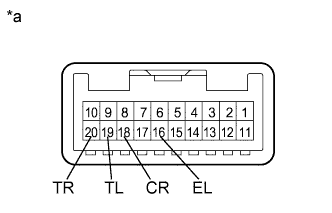
Text in Illustration *a Component without harness connected
(Headlight Dimmer Switch Assembly)
Measure the resistance according to the value(s) in the table below.
Standard Resistance Tester Connection Condition Specified Condition 20 (TR) - 16 (EL) Turn signal switch in neutral position 10 kΩ or higher 19 (TL) - 16 (EL) Turn signal switch in neutral position 10 kΩ or higher 18 (CR) - 16 (EL) Turn signal switch in neutral position 10 kΩ or higher 20 (TR) - 16 (EL) Turn signal switch in right turn position Below 1 Ω 18 (CR) - 16 (EL) Turn signal switch in full right turn position Below 1 Ω 19 (TL) - 16 (EL) Turn signal switch in left turn position Below 1 Ω 18 (CR) - 16 (EL) Turn signal switch in full left turn position Below 1 Ω Result Result Proceed to OK A NG (for TMC, TMMR Made) B NG (for TMMK Made) C
-
B 
REPLACE HEADLIGHT DIMMER SWITCH ASSEMBLY Click here
C
REPLACE HEADLIGHT DIMMER SWITCH ASSEMBLY Click here
A 
-
-
CHECK HARNESS AND CONNECTOR (HEADLIGHT DIMMER SWITCH ASSEMBLY - COMBINATION METER ASSEMBLY)
-
Disconnect the I17 combination meter assembly connector.
-
for LHD:
-
Measure the resistance according to the value(s) in the table below.
Standard Resistance Tester Connection Condition Specified Condition I25-12 (TR) - I17-9 (ER) Always Below 1 Ω I25-11 (TL) - I17-10 (EL) Always Below 1 Ω I25-13 (CR) - I17-8 (SW) Always Below 1 Ω I25-15 (EL) - Body ground Always Below 1 Ω I17-9 (ER) - Body ground Always 10 kΩ or higher I17-10 (EL) - Body ground Always 10 kΩ or higher I17-8 (SW) - Body ground Always 10 kΩ or higher
-
-
for RHD:
-
Measure the resistance according to the value(s) in the table below.
Standard Resistance Tester Connection Condition Specified Condition I25-20 (TR) - I17-9 (ER) Always Below 1 Ω I25-19 (TL) - I17-10 (EL) Always Below 1 Ω I25-18 (CR) - I17-8 (SW) Always Below 1 Ω I25-16 (EL) - Body ground Always Below 1 Ω I17-9 (ER) - Body ground Always 10 kΩ or higher I17-10 (EL) - Body ground Always 10 kΩ or higher I17-8 (SW) - Body ground Always 10 kΩ or higher
-
NG
REPAIR OR REPLACE HARNESS OR CONNECTOR
OK
PROCEED TO NEXT SUSPECTED AREA SHOWN IN PROBLEM SYMPTOMS TABLE Click here
-