OIL PUMP INSTALLATION

-
INSTALL TIMING CHAIN COVER SUB-ASSEMBLY
-
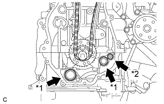
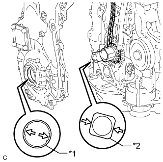
Text in Illustration *1 Oil Pump Gasket *2 Oil Hole Cover Gasket Apply a light coat of engine oil to 2 new oil pump gaskets and a new oil hole cover gasket.
-
Install the 2 oil pump gaskets and oil hole cover gasket to the stiffening crankcase assembly.
-
Text in Illustration *1 Drive Rotor Spline *2 Crankshaft Timing Sprocket Align the drive rotor spline and the crankshaft timing sprocket as shown in the illustration.
-
Apply seal packing in a line to the timing chain cover sub-assembly as shown in the following illustration.
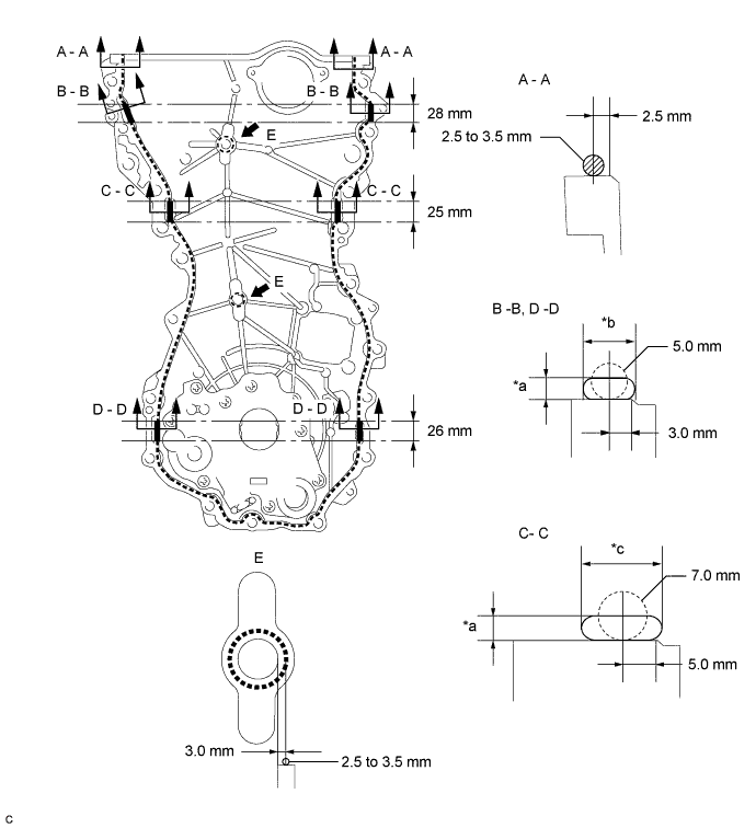
Text in Illustration *a 3.0 mm or more *b 7.0 mm or more *c 13 mm or more - - Seal Packing Toyota Genuine Seal Packing Black, Three Bond 1207B or equivalent. Seal Packing Application Chart Area Seal Packing Diameter (Round) Distance from Edge of Cover to Center of Seal Packing Seal Packing Application Length Seal Packing Dimension (Flat) Dashed Line 2.5 to 3.5 mm (0.0984 to 0.138 in.) 2.5 mm (0.0984 in.) - - A - A 2.5 to 3.5 mm (0.0984 to 0.138 in.) 2.5 mm (0.0984 in.) - - B - B 5.0 mm (0.197 in.) 3.0 mm (0.118 in.) 28 mm (1.10 in.) 7.0 mm (0.276 in.) or wider and 3.0 mm (0.118 in.) or thicker C - C 7.0 mm (0.276 in.) 5.0 mm (0.197 in.) 25 mm (0.984 in.) 13 mm (0.512 in.) or wider and 3.0 mm (0.118 in.) or thicker D - D 5.0 mm (0.197 in.) 3.0 mm (0.118 in.) 26 mm (1.02 in.) 7.0 mm (0.276 in.) or wider and 3.0 mm (0.118 in.) or thicker E 2.5 to 3.5 mm (0.0984 to 0.138 in.) 3.0 mm (0.118 in.) - - Note
-
Clean the surfaces with non-residue solvent before applying seal packing.
-
Install the timing chain cover sub-assembly within 3 minutes and tighten the bolts within 10 minutes of applying seal packing.
-
After applying seal packing to the timing chain cover sub-assembly, install the engine mounting bracket RH within 10 minutes.
-
Do not add oil for at least 2 hours after installation.
-
Do not start the engine for at least 2 hours after installation.
-
-
Temporarily install the timing chain cover sub-assembly with the 17 bolts and 2 nuts.
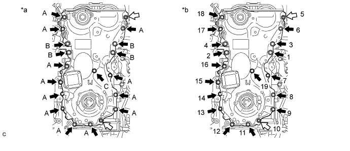
Text in Illustration *a Torque *b Tightening Order 
Bolt 
Nut Bolt Length Item Length Thread Diameter Bolt (A) 30 mm (1.18 in.) 8.0 mm (0.315 in.) Bolt (B) 35 mm (1.38 in.) 10 mm (0.394 in.) Bolt (C) 45 mm (1.77 in.) 8.0 mm (0.315 in.) Note
Make sure there is no oil on the bolts. If oil is found on any bolt, clean it before installation.
-
Tighten the 17 bolts and 2 nuts in several steps, in the order shown in the illustration.
- Torque:
- Bolt (A), (C) and Nut
- 21 N*m { 214 kgf*cm, 15 ft.*lbf }
- Bolt (B)
- 55 N*m { 561 kgf*cm, 41 ft.*lbf }
-
-
INSTALL ENGINE MOUNTING BRACKET RH
-
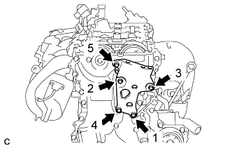
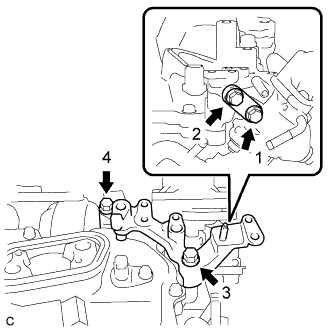
Install the engine mounting bracket RH with the 5 bolts in the order shown in the illustration.
- Torque:
- Bolt (1), (2) and (3)
- 55 N*m { 561 kgf*cm, 41 ft.*lbf }
- Bolt (4) and (5)
- 21 N*m { 214 kgf*cm, 15 ft.*lbf }
Note
After applying seal packing to the timing chain cover sub-assembly, install the engine mounting bracket RH within 10 minutes.
-
-
INSTALL TIMING CHAIN COVER OIL SEAL
-
Apply MP grease to the lip of a new timing chain cover oil seal.
Note
-
Keep the lip free from foreign matter.
-
Do not allow MP grease to contact the dust seal.
-
-
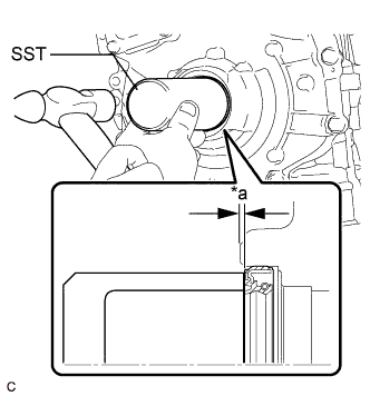
Text in Illustration *a Standard Depth (from edge of the timing chain cover sub-assembly) Using SST and a hammer, tap in the timing chain cover oil seal.
- SST
- 09636-20010
Standard Depth -0.75 to -1.45 mm (-0.0295 to -0.0571 in.) Note
-
Keep the lip free from foreign matter.
-
Do not tap in the timing chain cover oil seal at an angle.
-
-
INSTALL V-RIBBED BELT TENSIONER ASSEMBLY
-
Install the V-ribbed belt tensioner assembly with the bolt.
- Torque:
- 21 N*m { 214 kgf*cm, 15 ft.*lbf }
-
Install the dust cover to the V-ribbed belt tensioner assembly.
-
-
INSTALL CAMSHAFT TIMING OIL CONTROL SOLENOID ASSEMBLY
-
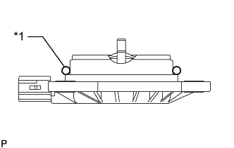
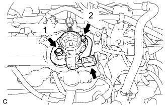
Text in Illustration *1 O-ring Apply engine oil to a new O-ring and install it to the camshaft timing oil control solenoid assembly as shown in the illustration.
Note
Do not damage the O-ring.
-
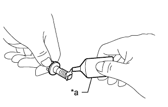
Text in Illustration *a Adhesive 1324 Apply adhesive to 2 or 3 threads of 2 new bolts.
Adhesive Toyota Genuine Adhesive 1324, Three Bond 1324 or equivalent. -
Install the camshaft timing oil control solenoid assembly to the timing chain cover sub-assembly with the 2 bolts.
- Torque:
- 10 N*m { 102 kgf*cm, 7 ft.*lbf }
Note
-
If the camshaft timing oil control solenoid assembly has been struck or dropped, replace it.
-
Make sure that the O-ring is not cracked or moved out of place when installing the camshaft timing oil control solenoid assembly.
-
Connect the camshaft timing oil control solenoid assembly connector.
-
-
INSTALL CRANKSHAFT PULLEY
-
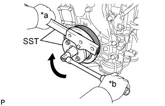
Text in Illustration *a Hold *b Turn Align the crankshaft pulley key with the key groove of the crankshaft pulley.
-
Using SST, hold the crankshaft pulley and install the crankshaft pulley set bolt.
- SST
- 09213-54015
- 09330-00021
- Torque:
- 260 N*m { 2651 kgf*cm, 192 ft.*lbf }
Tech Tips
Part number of installation bolt for SST (crankshaft pulley holding tool): 91551-80650 (quantity: 2)
-
-
INSTALL CRANKSHAFT POSITION SENSOR
-
Clean and degrease the threads of the bolt for the crankshaft position sensor.
-
Apply a light coat of engine oil to the O-ring of the crankshaft position sensor.
Note
If reusing the crankshaft position sensor, be sure to inspect the O-ring.
-
Text in Illustration *a Adhesive 1324 Apply adhesive to 2 or 3 threads of the bolt.
Adhesive Toyota Genuine Adhesive 1324, Three Bond 1324 or equivalent. -
Install the crankshaft position sensor to the timing chain cover sub-assembly with the bolt.
- Torque:
- 6.5 N*m { 66 kgf*cm, 58 in.*lbf }
Note
-
If the crankshaft position sensor has been struck or dropped, replace it.
-
Make sure that the O-ring is not cracked or moved out of place when installing the crankshaft position sensor.
-
Connect the crankshaft position sensor connector.
-
-
INSTALL CYLINDER HEAD COVER SUB-ASSEMBLY
-
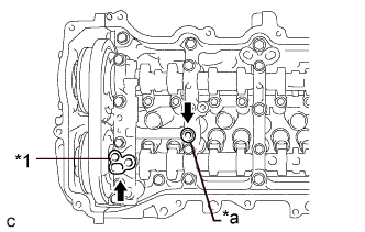
Text in Illustration *1 Camshaft Bearing Cap Oil Hole Gasket *a Gasket Apply a light coat of engine oil to a new camshaft bearing cap oil hole gasket and a new gasket.
-
Install the camshaft bearing cap oil hole gasket to the No. 1 camshaft bearing cap.
-
Install the gasket to the No. 2 camshaft bearing cap.
-
Install a new cylinder head cover gasket to the cylinder head cover sub-assembly.
Note
Remove any oil from the contact surface.
-
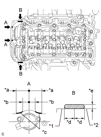
Text in Illustration *1 Timing Chain Cover Sub-assembly *2 Camshaft Housing Sub-assembly *a 45 mm (1.77 in.) *b 24 mm (0.945 in.) *c Seal Packing Diameter: 3.0 mm (0.118 in.) *d Application Width 5.0 mm (0.197 in.) *e Seal Packing Diameter: 3.0 to 6.0 mm (0.118 to 0.236 in.) Seal Packing Apply seal packing as shown in the illustration.
Seal Packing Toyota Genuine Seal Packing Black, Three Bond 1207B or equivalent Note
-
Remove any oil from the contact surface.
-
Install the cylinder head cover sub-assembly within 3 minutes and tighten the bolts within 15 minutes of applying seal packing.
-
-
Align the cylinder head cover sub-assembly with the pin (A). Then align the cylinder head cover sub-assembly with the pin (B) and install the cylinder head cover sub-assembly.
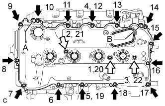
Text in Illustration Bolt Bolt with Seal Washer -
Install 3 new seal washers and the 17 bolts, and then tighten the bolts in the order shown in the illustration.
- Torque:
- 12 N*m { 122 kgf*cm, 9 ft.*lbf }
Note
Do not start the engine for at least 2 hours after installation.
-
-
INSTALL EGR VALVE BRACKET
-
Temporarily install the 2 EGR valve brackets with the 4 bolts.
-
Tighten the 4 bolts in the order shown in the illustration.
- Torque:
- 21 N*m { 214 kgf*cm, 15 ft.*lbf }
-
Install the fuel hose bracket to the EGR valve bracket with the engine cover joint.
- Torque:
- 13 N*m { 133 kgf*cm, 10 ft.*lbf }
-
-
TEMPORARILY INSTALL FUEL PUMP WITH SEAL SUB-ASSEMBLY
-
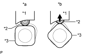
Text in Illustration *1 Fuel Pump Lifter Guide *2 Fuel Pump Lifter Assembly *3 Camshaft *a Correct *b Incorrect Turn the crankshaft pulley until the flat of the camshaft faces the fuel pump with seal sub- assembly installation hole of the cylinder head cover sub-assembly.
Tech Tips
This prevent the camshaft nose from pushing up the fuel pump lifter assembly when installing the fuel pump with seal sub-assembly.
-
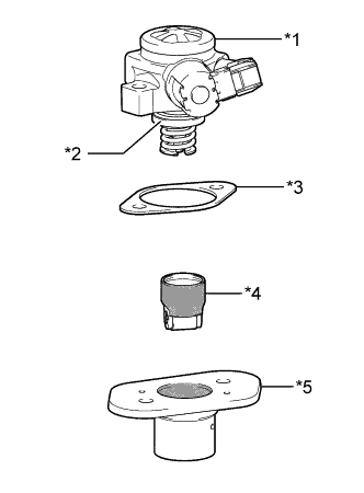
Text in Illustration *1 Fuel Pump with Seal Sub-assembly *2 O-ring *3 Fuel Pump Insulator *4 Fuel Pump Lifter Assembly *5 Fuel Pump Lifter Guide 
Engine Oil Application Area Apply engine oil to a new O-ring and install it to the fuel pump sub-assembly.
-
Apply engine oil to the inside of the fuel pump lifter guide and the outside of the fuel pump lifter assembly.
-
Install the fuel pump lifter assembly to the fuel pump lifter guide.
-
Install the fuel pump insulator to the fuel pump lifter guide.
-
Install the fuel pump with seal sub-assembly to the fuel pump lifter guide.
-
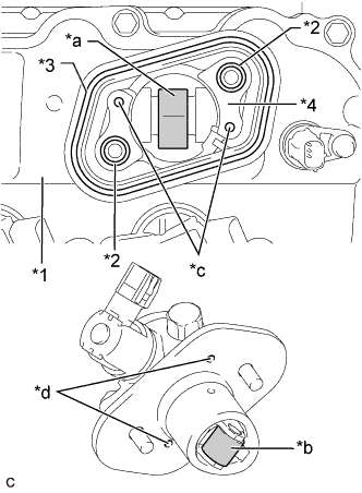
Text in Illustration *1 Cylinder Head Cover Sub-assembly *2 O-ring *3 Fuel Pump Spacer Gasket *4 No. 4 Camshaft Bearing Cap *a Pump Drive Cam (Engine Oil Application Area) *b Pump Lifter (Engine Oil Application Area) *c Knock Pin *d Pin Hole Apply 30 cc (1.8 cu. in.) of engine oil to the pump drive cam.
-
Apply engine oil to the fuel pump lifter assembly.
-
Apply engine oil to 2 new O-rings and install them to the No. 4 camshaft bearing cap.
-
Install a new fuel pump spacer gasket to the cylinder head cover sub-assembly.
-
Set the fuel pump with seal sub-assembly on the cylinder head cover sub-assembly.
-
Temporarily install the fuel pump with seal sub-assembly with the 2 bolts, leaving some allowance for left and right movement.
-
-
TEMPORARILY INSTALL NO. 1 FUEL PIPE SUB-ASSEMBLY
-
Connect the No. 1 fuel pipe sub-assembly to the fuel delivery pipe sub-assembly and tighten the union nut by hand.
-
Connect the No. 1 fuel pipe sub-assembly to the fuel pump with seal sub-assembly and tighten the union nut by hand.
Note
Do not damage the seals of the union nuts of the No. 1 fuel pipe sub-assembly when installing.
-
-
INSTALL FUEL PUMP WITH SEAL SUB-ASSEMBLY
Tech Tips
Perform "Inspection After Repair" after replacing the fuel pump with seal sub-assembly Click here.
-
Tighten the 2 bolts in the order shown in the illustration.
- Torque:
- 30 N*m { 306 kgf*cm, 22 ft.*lbf }
-
Connect the fuel pump with seal sub-assembly connector.
-
-
INSTALL NO. 1 FUEL PIPE SUB-ASSEMBLY
-
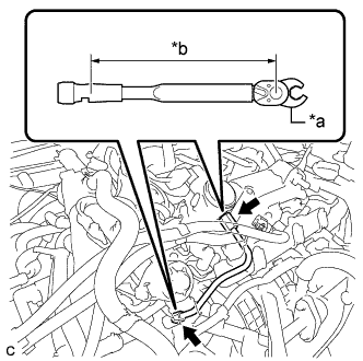
Text in Illustration *a 17 mm Union Nut Wrench *b Torque Wrench Fulcrum Length Using a 17 mm union nut wrench, tighten the union nuts on the fuel pump with seal sub-assembly side of the No. 1 fuel pipe sub-assembly.
- Torque:
- 35 N*m { 357 kgf*cm, 26 ft.*lbf }
Tech Tips
-
Calculate the torque wrench reading when changing the fulcrum length of the torque wrench Click here.
-
When using a 17 mm union nut wrench (fulcrum length of 30 mm (1.18 in.)) + torque wrench (fulcrum length of 180 mm (7.09 in.)): 30 N*m (306 kgf*cm, 22 ft.*lbf)
-
Using a 17 mm union nut wrench, tighten the union nuts on the fuel delivery pipe sub-assembly side of the No. 1 fuel pipe sub-assembly.
- Torque:
- 35 N*m { 357 kgf*cm, 26 ft.*lbf }
Tech Tips
-
Calculate the torque wrench reading when changing the fulcrum length of the torque wrench Click here.
-
When using a 17 mm union nut wrench (fulcrum length of 30 mm (1.18 in.)) + torque wrench (fulcrum length of 180 mm (7.09 in.)): 30 N*m (306 kgf*cm, 22 ft.*lbf)
-
-
INSTALL NO. 1 FUEL PIPE
-
Install the No. 1 fuel pipe and a new gasket to the fuel pump with seal sub-assembly.
- Torque:
- 40 N*m { 408 kgf*cm, 30 ft.*lbf }
-
-
CONNECT FUEL TUBE SUB-ASSEMBLY
Note
Check that there is no damage or foreign matter on the connecting parts of the fuel lines.
-
Connect the fuel tube sub-assembly to the No. 1 fuel pipe.
-
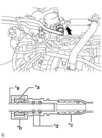
Text in Illustration *a Retainer *b Fuel Tube Connector *c Nylon Tube *d O-ring *e Fuel Pipe Push Align the fuel tube connector with the fuel pipe, and push them together until the fuel tube connector makes a "click" sound. If it is difficult to push the fuel pipe into the fuel tube connector, apply a small amount of clean engine oil to the tip of the fuel pipe and reinsert it.
-
After connecting the fuel pipes, check that the fuel pipe and fuel tube connector are securely connected by pulling on them.
-
Push in the fuel tube connector cover.
-
-
-
INSTALL FUEL PUMP PROTECTOR
-
Install the fuel pump protector to the cylinder head cover sub-assembly with the 2 bolts.
- Torque:
- 21 N*m { 214 kgf*cm, 15 ft.*lbf }
-
-
CONNECT NO. 2 VENTILATION HOSE
-
Connect the No. 2 ventilation hose to the PCV valve (ventilation valve sub-assembly) and slide the clip to secure it.
-
-
INSTALL IGNITION COIL ASSEMBLY
Tech Tips
Perform "Inspection After Repair" after replacing an ignition coil assembly Click here.
-
Install the 4 ignition coil assemblies to the cylinder head cover sub-assembly with the 4 bolts.
- Torque:
- 10 N*m { 102 kgf*cm, 7 ft.*lbf }
Note
If an ignition coil assembly has been struck or dropped, replace it.
Tech Tips
Install the same parts to their original positions.
-
Connect the 4 ignition coil assembly connectors.
-
-
REMOVE ENGINE ASSEMBLY FROM ENGINE STAND