OIL PUMP REMOVAL

Note
Do not remove the oil pump or oil pump relief valve from the timing chain cover sub-assembly.
-
INSTALL ENGINE ASSEMBLY TO ENGINE STAND
-
REMOVE IGNITION COIL ASSEMBLY
-
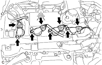
Disconnect the 4 ignition coil assembly connectors.
-
Remove the 4 bolts and 4 ignition coil assemblies from the cylinder head cover sub-assembly.
Note
If an ignition coil assembly has been struck or dropped, replace it.
Tech Tips
Arrange the removed parts in the correct order.
-
-
DISCONNECT NO. 2 VENTILATION HOSE
-
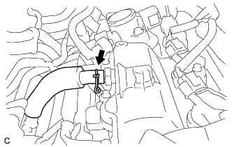
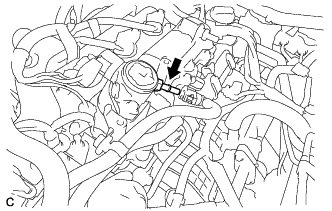
Slide the clip and disconnect the No. 2 ventilation hose from the PCV valve (ventilation valve sub-assembly).
-
-
REMOVE FUEL PUMP PROTECTOR
-
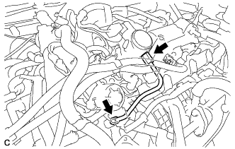
Remove the 2 bolts and fuel pump protector from the cylinder head cover sub-assembly.
-
-
DISCONNECT FUEL TUBE SUB-ASSEMBLY
Note
Remove any foreign matter on the fuel tube connector and fuel pipe before performing this work.
-
Disconnect the fuel tube sub-assembly from the No. 1 fuel pipe.
-
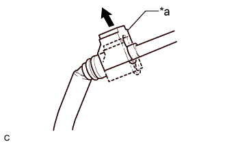
Text in Illustration *a Fuel Tube Connector Cover 
Pull off Pull off the fuel tube connector cover.
-
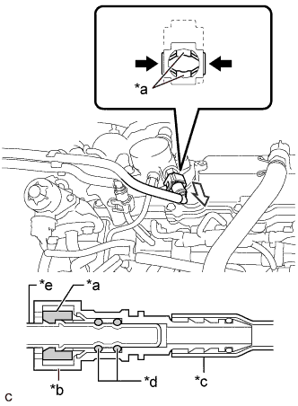
Text in Illustration *a Retainer *b Fuel Tube Connector *c Nylon Tube *d O-ring *e Fuel Pipe Pinch 
Pull Pinch the retainer of the fuel tube connector, and then pull the fuel tube connector off of the fuel pipe.
Note
Be sure to disconnect the fuel tube connector by hand.
-
If the fuel tube connector and fuel pipe are stuck, push and pull the fuel tube connector to release it. Pull the fuel tube connector off of the fuel pipe carefully.
Note
-
Be sure to disconnect the fuel tube connector by hand.
-
Do not scratch or allow any foreign matter to get on the parts when disconnecting them as the fuel tube connector has O-rings that seal the pipe (fuel pipe).
-
Do not bend, twist, pinch or kink the nylon tube.
-
-
Check that there is no foreign matter on the sealing surfaces of the disconnected fuel lines. Clean them if necessary.
-
Cover the disconnected fuel pipe and fuel tube connector with plastic bags to prevent damage and contamination.
-
-
-
REMOVE NO. 1 FUEL PIPE
-
Remove the No. 1 fuel pipe and gasket from the fuel pump with seal sub-assembly.
-
-
REMOVE NO. 1 FUEL PIPE SUB-ASSEMBLY
-
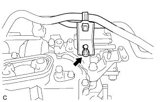
Using a 17 mm union nut wrench, loosen the 2 union nuts of the No. 1 fuel pipe sub-assembly.
-
Loosen the 2 bolts of the fuel pump with seal sub- assembly.
-
Remove the No. 1 fuel pipe sub-assembly from the fuel delivery pipe sub-assembly and fuel pump with seal sub- assembly.
-
-
REMOVE FUEL PUMP WITH SEAL SUB-ASSEMBLY
-
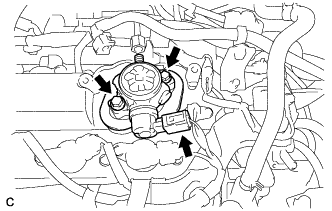
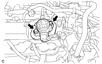
Disconnect the fuel pump with seal sub-assembly connector.
-
Remove the 2 bolts and fuel pump with seal sub- assembly from the cylinder head cover sub- assembly.
-
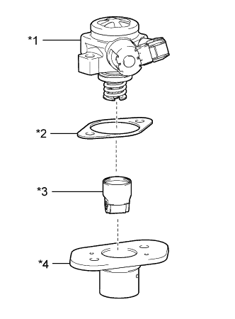
Text in Illustration *1 Fuel Pump with Seal Sub-assembly *2 Fuel Pump Insulator *3 Fuel Pump Lifter Assembly *4 Fuel Pump Lifter Guide Remove the fuel pump lifter guide, fuel pump lifter assembly and fuel pump insulator from the fuel pump with seal sub-assembly.
-
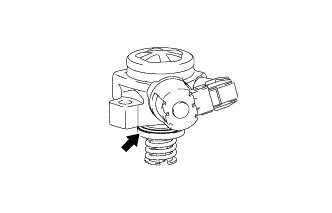
Remove the O-ring from the fuel pump sub- assembly.
-
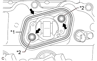
Text in Illustration *1 Fuel Pump Spacer Gasket *2 O-ring Remove the fuel pump spacer gasket from the cylinder head cover sub-assembly.
-
Remove the 2 O-rings from the No. 4 camshaft bearing cap.
-
-
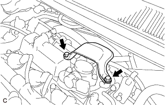
REMOVE EGR VALVE BRACKET
-
Remove the engine cover joint and separate the fuel hose bracket from the EGR valve bracket.
-
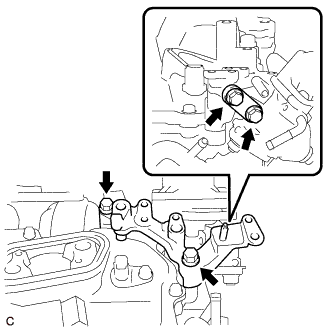
Remove the 4 bolts and 2 EGR valve brackets.
-
-
REMOVE CYLINDER HEAD COVER SUB-ASSEMBLY
-
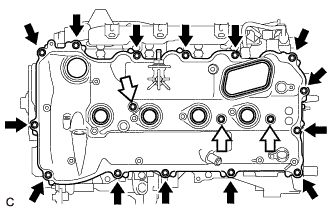
Remove the 17 bolts, 3 seal washers, cylinder head cover sub-assembly and cylinder head cover gasket.
Text in Illustration Bolt Bolt with Seal Washer -
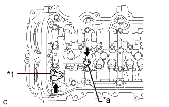
Text in Illustration *1 Camshaft Bearing Cap Oil Hole Gasket *a Gasket Remove the camshaft bearing cap oil hole gasket from the No. 1 camshaft bearing cap.
-
Remove the gasket from the No. 2 camshaft bearing cap.
-
-
REMOVE CRANKSHAFT POSITION SENSOR
-
Disconnect the crankshaft position sensor connector.
-
Remove the bolt and crankshaft position sensor.
-
-
REMOVE CRANKSHAFT PULLEY
-
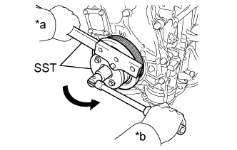
Text in Illustration *a Hold *b Turn Using SST, hold the crankshaft pulley and loosen the crankshaft pulley set bolt. Further loosen the crankshaft pulley set bolt until 2 or 3 threads are screwed into the crankshaft.
- SST
- 09213-54015
- 09330-00021
Tech Tips
Part number of installation bolt for SST (crankshaft pulley holding tool): 91551-80650 (quantity: 2)
-
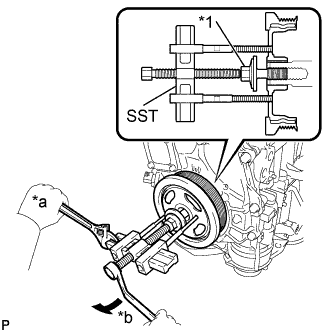
Text in Illustration *1 Crankshaft Pulley Set Bolt *a Hold *b Turn Using SST and the crankshaft pulley set bolt, remove the crankshaft pulley and crankshaft pulley set bolt.
- SST
- 09950-50013 ( 09951-05010, 09952-05010, 09953-05020, 09954-05011 )
Tech Tips
Apply lubricant to the threads and end of SST.
-
-
REMOVE CAMSHAFT TIMING OIL CONTROL SOLENOID ASSEMBLY
-
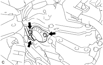
Disconnect the camshaft timing oil control solenoid assembly connector.
-
Remove the 2 bolts and camshaft timing oil control solenoid assembly from the timing chain cover sub-assembly.
Note
If the camshaft timing oil control solenoid assembly has been struck or dropped, replace it.
-
Remove the O-ring from the camshaft timing oil control solenoid assembly.
Note
-
If the O-ring comes off in the timing chain cover sub-assembly, make sure to remove it.
-
Do not drop the O-ring into the timing chain cover sub-assembly.
-
-
-
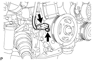
REMOVE V-RIBBED BELT TENSIONER ASSEMBLY
-
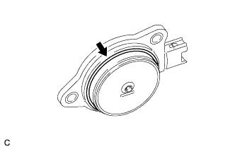
Remove the dust cover from the V-ribbed belt tensioner assembly.
-
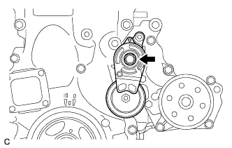
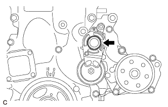
Remove the bolt and V-ribbed belt tensioner assembly from the water inlet housing.
-
-
REMOVE ENGINE MOUNTING BRACKET RH
-
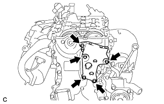
Remove the 5 bolts and engine mounting bracket RH.
-
-
REMOVE TIMING CHAIN COVER SUB-ASSEMBLY
-
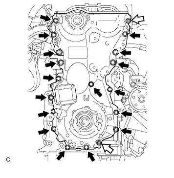
Remove the 17 bolts and 2 nuts.
Text in Illustration Bolt Nut -
Remove the timing chain cover sub-assembly by prying between the timing chain cover sub-assembly and cylinder head sub-assembly, camshaft housing sub-assembly, cylinder block and stiffening crankcase assembly with a screwdriver as shown in the illustration.
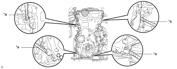
Text in Illustration *a Protective Tape - - Note
Be careful not to damage the contact surfaces of the cylinder head sub-assembly, camshaft housing sub-assembly, cylinder block, stiffening crankcase assembly or timing chain cover sub-assembly.
Tech Tips
Tape the screwdriver tip before use.
-
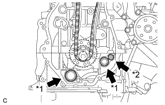
Text in Illustration *1 Oil Pump Gasket *2 Oil Hole Cover Gasket Remove the 2 oil pump gaskets and oil hole cover gasket from the stiffening crankcase assembly.
-
-
REMOVE TIMING CHAIN COVER OIL SEAL
-
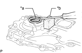
Text in Illustration *a Protective Tape *b Wooden Block Using a screwdriver and wooden block, pry out the timing chain cover oil seal.
Note
Do not damage the surface of the timing chain cover oil seal press fit hole.
Tech Tips
Tape the screwdriver tip before use.
-