EXHAUST MANIFOLD INSTALLATION

-
INSTALL STUD BOLT
Tech Tips
If a stud bolt is deformed or the threads are damaged, replace it.
-
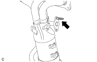
Using an E8 "TORX" socket wrench, install the stud bolt to the exhaust manifold converter sub-assembly (TWC: Front Catalyst).
- Torque:
- 9.5 N*m { 97 kgf*cm, 84 in.*lbf }
-
-
INSTALL NO. 2 EXHAUST MANIFOLD HEAT INSULATOR
-
Install the No. 2 exhaust manifold heat insulator to the exhaust manifold converter sub-assembly (TWC: Front Catalyst) with the 2 bolts.
- Torque:
- 13.5 N*m { 138 kgf*cm, 10 ft.*lbf }
-
-
INSTALL NO. 1 MANIFOLD CONVERTER INSULATOR
-
Install the No. 1 manifold converter insulator to the exhaust manifold converter sub-assembly (TWC: Front Catalyst) with the 3 bolts.
- Torque:
- 13.5 N*m { 138 kgf*cm, 10 ft.*lbf }
-
-
INSTALL EXHAUST MANIFOLD CONVERTER SUB-ASSEMBLY (TWC: Front Catalyst)
-
Install a new exhaust manifold gasket to the cylinder head sub-assembly.
-
Temporarily install the exhaust manifold converter sub-assembly (TWC: Front Catalyst) to the cylinder head sub-assembly with the 5 nuts.
-
Install 2 new EGR cooler gaskets to the EGR pipe connector.
-
Temporarily install the EGR pipe connector to the exhaust manifold converter sub-assembly (TWC: Front Catalyst), EGR cooler assembly and cylinder block sub-assembly with the 4 bolts and nut.
-
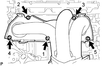
Tighten the 5 nuts in the order shown in the illustration.
- Torque:
- 62 N*m { 632 kgf*cm, 46 ft.*lbf }
-
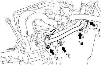
Text in Illustration *a Bolt (A) *b Bolt (B) 
Bolt 
Nut Tighten the 4 bolts and nut.
- Torque:
- Bolt (A) and Nut
- 36 N*m { 367 kgf*cm, 27 ft.*lbf }
- Bolt (B)
- 10 N*m { 102 kgf*cm, 7 ft.*lbf }
-
-
INSTALL NO. 2 MANIFOLD STAY
-
Install the No. 2 manifold stay to the exhaust manifold converter sub-assembly (TWC: Front Catalyst) and stiffening crankcase assembly with the bolt and nut.
- Torque:
- 43 N*m { 438 kgf*cm, 32 ft.*lbf }
-
-
INSTALL MANIFOLD STAY
-
Install the manifold stay to the exhaust manifold converter sub-assembly (TWC: Front Catalyst) and stiffening crankcase assembly with the bolt and nut.
- Torque:
- 43 N*m { 438 kgf*cm, 32 ft.*lbf }
-
-
INSTALL AIR FUEL RATIO SENSOR
Tech Tips
Perform "Inspection After Repair" after replacing the air fuel ratio sensor Click here.
-
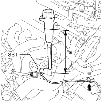
Text in Illustration *a Torque Wrench Fulcrum Length Using SST, install the air fuel ratio sensor to the exhaust manifold.
- SST
- 09224-00011
- Torque:
- Specified tightening torque
- 44 N*m { 449 kgf*cm, 32 ft.*lbf }
Note
If the air fuel ratio sensor has been struck or dropped, replace it.
Tech Tips
-
Calculate the torque wrench reading when changing the fulcrum length of the torque wrench Click here.
-
When using SST (fulcrum length of 30 mm (1.18 in.)) + torque wrench (fulcrum length of 260 mm (10.2 in.)): 39 N*m (398 kgf*cm, 29 ft.*lbf)
-
Connect the air fuel ratio sensor connector.
-
Engage the 3 wire harness clamps.
-
-
INSTALL NO. 1 EXHAUST MANIFOLD HEAT INSULATOR
-
Install the No. 1 exhaust manifold heat insulator to the exhaust manifold converter sub-assembly (TWC: Front Catalyst) with the 4 bolts.
- Torque:
- 12 N*m { 122 kgf*cm, 9 ft.*lbf }
-
-
INSTALL INLET AIR CLEANER ASSEMBLY
-
Install the inlet air cleaner assembly with the 2 bolts.
- Torque:
- 8.0 N*m { 82 kgf*cm, 71 in.*lbf }
-
-
INSTALL FRONT EXHAUST PIPE ASSEMBLY (TWC: Rear Catalyst)
-
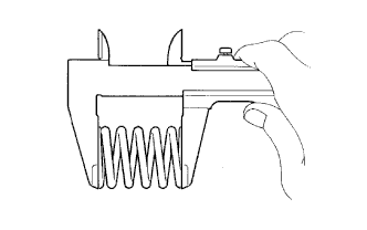
Using a vernier caliper, measure the free length of the 2 compression springs.
Minimum Free Length 40.5 mm (1.59 in.) If the free length is less than the minimum, replace the compression spring.
-
Temporarily install a new exhaust pipe gasket to the exhaust manifold converter sub-assembly (TWC: Front Catalyst).
-
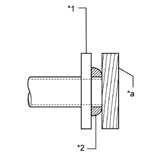
Text in Illustration *1 Exhaust Manifold Converter Sub-assembly (TWC: Front Catalyst) *2 Exhaust Pipe Gasket *a Wooden Block Using a plastic hammer and wooden block, tap in the exhaust pipe gasket until its surface is flush with the exhaust manifold converter sub-assembly (TWC: Front Catalyst).
Note
-
Be careful with the installation direction of the gasket.
-
Do not reuse the gasket.
-
Do not damage the gasket.
-
Do not push in the gasket by using the exhaust pipe when connecting it.
-
-
Install a new exhaust pipe gasket to the front exhaust pipe assembly (TWC: Rear Catalyst).
-
Connect the front exhaust pipe assembly (TWC: Rear Catalyst) to the exhaust pipe support.
-
Install the front exhaust pipe assembly (TWC: Rear Catalyst) to the exhaust manifold converter sub-assembly (TWC: Front Catalyst) and center exhaust pipe assembly with the 2 compression springs, 2 bolts and 2 nuts.
- Torque:
- 43 N*m { 438 kgf*cm, 32 ft.*lbf }
Tech Tips
After installation, check that the space between the flanges of the exhaust manifold converter sub-assembly (TWC: Front Catalyst) and front exhaust pipe assembly (TWC: Rear Catalyst) is consistent front-to-rear and left-to-right.
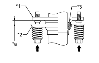
Text in Illustration *1 Exhaust Manifold Converter Sub-assembly (TWC: Front Catalyst) *2 Front Exhaust Pipe Assembly (TWC: Rear Catalyst) *3 Exhaust Pipe Gasket *a Space between Flanges: 8.5 mm (0.335 in.) -
Connect the heated oxygen sensor connector.
-
-
INSPECT FOR EXHAUST GAS LEAK
If gas is leaking, tighten the areas necessary to stop the leak. Replace damaged parts as necessary.
-
Perform Inspection After Repair after repairing an exhaust gas leak Click here.
-
-
INSTALL ENGINE UNDER COVER LH
-
Install the engine under cover LH with the 3 screws and 2 clips.
-
-
INSTALL FRONT WHEEL OPENING EXTENSION PAD LH
-
Install the front wheel opening extension pad LH with the 3 screws.
-
-
INSTALL ENGINE UNDER COVER RH
-
Install the engine under cover RH with the 3 screws and 3 clips.
-
-
INSTALL FRONT WHEEL OPENING EXTENSION PAD RH
-
Install the front wheel opening extension pad RH with the 3 screws.
-