INTAKE MANIFOLD INSTALLATION
-
INSTALL INTAKE MANIFOLD
-
Install a new manifold gasket to the intake manifold.
-
Temporarily install the intake manifold to the cylinder head sub-assembly with the 6 bolts.
-
Install a new EGR inlet gasket to the intake manifold.
-
Install a new No. 2 EGR pipe gasket to the EGR valve assembly.
-
Temporarily install the No. 2 EGR pipe to the EGR valve assembly and intake manifold with the 4 bolts.
-
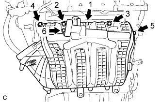
Tighten the 6 bolts in the order shown in the illustration.
- Torque:
- 28 N*m { 286 kgf*cm, 21 ft.*lbf }
-
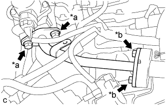
Text in Illustration *a Bolt (A) *b Bolt (B) Tighten the 4 bolts.
- Torque:
- Bolt (A)
- 25 N*m { 255 kgf*cm, 18 ft.*lbf }
- Bolt (B)
- 10 N*m { 102 kgf*cm, 7 ft.*lbf }
-
Engage the 2 wire harness clamps to the No. 2 EGR pipe.
-
-
CONNECT ENGINE WIRE
-
Engage the 7 wire harness clamps to the intake manifold.
-
-
INSTALL FUEL PUMP PROTECTOR
-
Install the fuel pump protector to the cylinder head cover sub-assembly with the 2 bolts.
- Torque:
- 21 N*m { 214 kgf*cm, 15 ft.*lbf }
-
-
INSTALL PURGE VALVE (PURGE VSV)
-
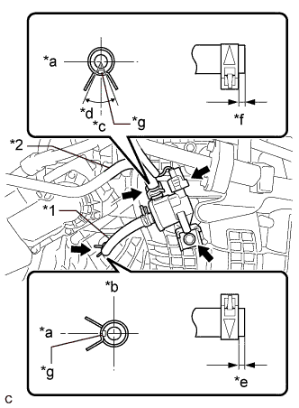
Text in Illustration *1 Fuel Vapor Hose *2 Fuel Vapor Feed Hose Assembly *a Left *b Upper *c Back *d 60° *e 4 to 9 mm (0.157 to 0.354 in.) *f 2 to 7 mm (0.0787 to 0.276 in.) *g Paint Mark Install the purge valve (purge VSV) to the intake manifold with the bolt.
- Torque:
- 10 N*m { 102 kgf*cm, 7 ft.*lbf }
-
Connect the purge valve (purge VSV) connector.
-
Connect the fuel vapor feed hose assembly to the purge valve (purge VSV) and slide the clip to secure it.
-
Connect the fuel vapor hose to the intake manifold and slide the clip to secure it.
Tech Tips
Make sure the direction of the clip is as shown in the illustration.
-
-
INSTALL VACUUM SENSOR (MANIFOLD ABSOLUTE PRESSURE SENSOR)
-
Install the vacuum sensor (manifold absolute pressure sensor) to the intake manifold with the bolt.
- Torque:
- 10 N*m { 102 kgf*cm, 7 ft.*lbf }
-
Connect the vacuum hose to the intake manifold.
-
Connect the vacuum sensor (manifold absolute pressure sensor) connector.
-
-
CONNECT NO. 2 VENTILATION HOSE
-
Connect the No. 2 ventilation hose to the intake manifold and slide the clip to secure it.
-
-
INSTALL THROTTLE BODY WITH MOTOR ASSEMBLY
-
INSTALL FRONT OUTER COWL TOP PANEL SUB-ASSEMBLY
-
Install the front outer cowl top panel sub-assembly with the 10 bolts.
- Torque:
- 10 N*m { 102 kgf*cm, 7 ft.*lbf }
-
Engage the 2 clamps to install the wire harness to the front outer cowl top panel sub-assembly.
-
w/ Windshield Deicer System:
-
Connect the connector.
-
Engage the 2 clamps to install the wire harness to the front outer cowl top panel sub-assembly.
-
-
w/ Heated Windshield Defroster System:
-
Connect the 2 connectors.
-
Engage the 4 clamps to install the wire harness to the front outer cowl top panel sub-assembly.
-
-
-
INSTALL WINDSHIELD WIPER MOTOR AND LINK ASSEMBLY