EGR VALVE INSTALLATION
-
INSTALL EGR VALVE ASSEMBLY
Tech Tips
After replacing the EGR valve assembly, perform the Inspection After Repairs Click here.
-
Install a new EGR valve gasket to the EGR valve assembly.
-
Install the EGR valve assembly to the EGR cooler assembly with the 2 nuts.
- Torque:
- 25 N*m { 255 kgf*cm, 18 ft.*lbf }
-
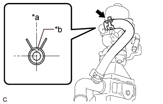
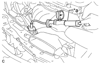
Text in Illustration *a Upper
(When the EGR valve assembly is installed on the engine assembly)
*b Paint Mark Connect the No. 1 water by-pass hose to the EGR valve assembly and slide the clip to secure it.
Tech Tips
Make sure the direction of the clip is as shown in the illustration.
-
-
INSTALL EGR VALVE WITH COOLER ASSEMBLY
-
Install a new No. 2 EGR pipe gasket to the EGR valve assembly.
-
Install a new EGR cooler gasket to the EGR pipe connector.
-
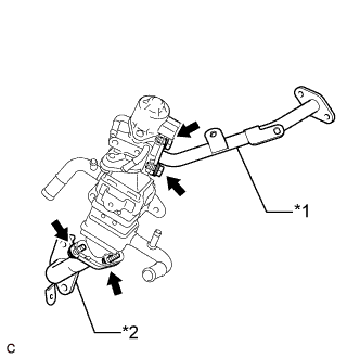
Text in Illustration *1 No. 2 EGR Pipe *2 EGR Pipe Connector Temporarily connect the No. 2 EGR pipe to the EGR valve assembly with the 2 bolts.
-
Temporarily connect the EGR pipe connector to the EGR cooler assembly with the 2 bolts.
-
Install a new EGR cooler gasket to the EGR pipe connector.
-
Install a new EGR inlet gasket to the intake manifold.
-
Temporarily install the EGR valve with cooler assembly, No. 2 EGR pipe and EGR pipe connector to the cylinder head sub-assembly, cylinder block sub-assembly, intake manifold and exhaust manifold converter sub-assembly (TWC: Front Catalyst) with the 4 bolts and 3 nuts.
-
Tighten the 8 bolts and 3 nuts in the order shown in the illustration.
Text in Illustration *a Bolt (A) *b Bolt (B) *c Bolt (C) *d Nut (A) *e Nut (B) - - 
Bolt 
Nut - Torque:
- Bolt (A) and Nut (B)
- 36 N*m { 367 kgf*cm, 27 ft.*lbf }
- Bolt (B)
- 25 N*m { 255 kgf*cm, 18 ft.*lbf }
- Bolt (C)
- 10 N*m { 102 kgf*cm, 7 ft.*lbf }
- Nut (A)
- 21 N*m { 214 kgf*cm, 15 ft.*lbf }
-
Engage the 2 wire harness clamps to the No. 2 EGR pipe.
-
Temporarily install the 2 EGR valve brackets with the 4 bolts.
-
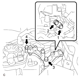
Tighten the 4 bolts in the order shown in the illustration.
- Torque:
- 21 N*m { 214 kgf*cm, 15 ft.*lbf }
-
Install the fuel hose bracket to the EGR valve bracket with the engine cover joint.
- Torque:
- 13 N*m { 133 kgf*cm, 10 ft.*lbf }
-
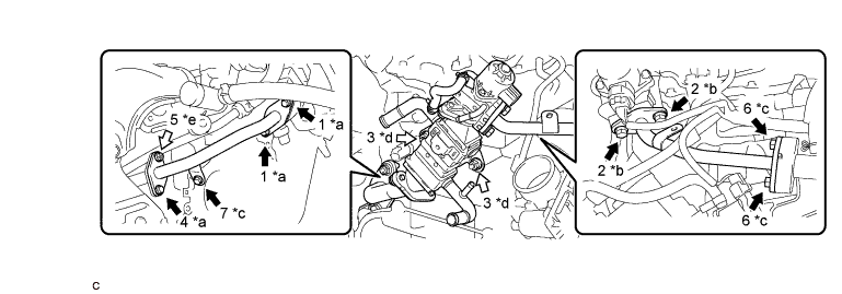
Connect the No. 4 water by-pass hose to the EGR cooler assembly and slide the clip to secure it.
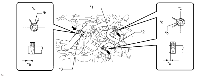
Text in Illustration *1 No. 2 Water By-pass Hose *2 No. 3 Water By-pass Hose *3 No. 4 Water By-pass Hose - - *a 1 to 6 mm (0.0394 to 0.236 in.) *b Paint Mark *c Upper *d Left Tech Tips
Make sure the direction of the clip is as shown in the illustration.
-
Connect the No. 3 water by-pass hose to the EGR cooler assembly and slide the clip to secure it.
Tech Tips
Make sure the direction of the clip is as shown in the illustration.
-
Connect the No. 2 water by-pass hose to the EGR valve assembly and slide the clip to secure it.
Tech Tips
Make sure the direction of the clip is as shown in the illustration.
-
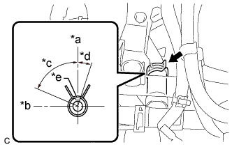
Text in Illustration *a Upper *b Front *c 75° *d 15° *b Paint Mark Connect the water hose sub-assembly to the EGR cooler assembly and slide the clip to secure it.
Tech Tips
Engage the clip within the area shown in the illustration.
-
Engage the water hose to the hose clamp.
-
Connect the EGR valve assembly connector.
-
-
CONNECT ENGINE WIRE
-
Connect the engine coolant temperature sensor connector.
-
Install the bolt.
- Torque:
- 8.0 N*m { 82 kgf*cm, 71 in.*lbf }
-
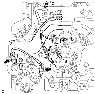
Text in Illustration *a Fuel Pump Sub-assembly Connector *b Ignition Coil Assembly Connector *c Camshaft Position Sensor Connector Bolt Nut Engage the clamp.
-
Connect the fuel pump sub-assembly connector.
-
Connect the ignition coil assembly connector.
-
Connect the 2 camshaft position sensor connectors.
-
Install the nut.
- Torque:
- 8.0 N*m { 82 kgf*cm, 71 in.*lbf }
-
Connect the 2 earth wires to the EGR valve bracket with the 2 bolts.
- Torque:
- 8.0 N*m { 82 kgf*cm, 71 in.*lbf }
-
-
INSTALL FUEL PUMP PROTECTOR
-
Install the fuel pump protector to the cylinder head cover sub-assembly with the 2 bolts.
- Torque:
- 21 N*m { 214 kgf*cm, 15 ft.*lbf }
-
-
INSTALL AIR CLEANER CASE SUB-ASSEMBLY
-
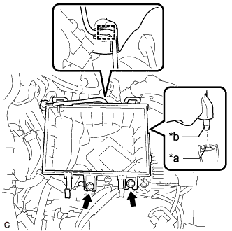
Text in Illustration *a Hole *b Projection Insert the projection of the air cleaner case sub-assembly into the hole of the No. 1 air cleaner bracket as shown in the illustration.
-
Install the 2 bolts.
- Torque:
- 5.0 N*m { 51 kgf*cm, 44 in.*lbf }
-
Connect the wire harness clamp.
-
-
INSTALL AIR CLEANER FILTER ELEMENT SUB-ASSEMBLY
-
Install the air cleaner filter element sub-assembly to the air cleaner case sub-assembly.
Note
Install the air cleaner filter element sub-assembly with the printed side facing the vehicle left.
-
-
INSTALL AIR CLEANER CAP WITH AIR CLEANER HOSE
-
Connect the air cleaner cap with air cleaner hose to the throttle body with motor assembly.
-
Install the air cleaner cap with air cleaner hose with the 2 guides and 2 air cleaner cap clamps.
-
Tighten the hose clamp.
-
Connect the union to connector tube hose to the air cleaner hose sub-assembly.
-
Engage the wire harness clamp.
-
Connect the mass air flow meter sub-assembly connector.
-
Engage the ventilation hose clamp.
-
Connect the ventilation hose to the cylinder head cover sub-assembly and slide the clip to secure it.
-
-
ADD ENGINE COOLANT (for Engine)
-
Tighten the radiator drain cock plug by hand.
-
Slowly fill the radiator assembly with engine coolant.
Specified Capacity 7.3 liters (7.7 US qts, 6.4 Imp. qts) Note
Do not substitute plain water for engine coolant.
Tech Tips
TOYOTA vehicles are filled with TOYOTA SLLC at the factory. In order to avoid damaging the engine cooling system and other technical problems, only use TOYOTA SLLC or similar high quality ethylene glycol based non-silicate, non-amine, non-nitrite, non-borate coolant with long-life hybrid organic acid technology (coolant with long-life hybrid organic acid technology is a combination of low phosphates and organic acids).
-
Remove the reserve tank cap.
-
Slowly pour engine coolant into the radiator reserve tank assembly until it reaches the full line.
-
Squeeze the No. 1 radiator hose and No. 2 radiator hose several times by hand, and then check the level of the engine coolant.
If the engine coolant level is low, add engine coolant.
-
Install the radiator cap sub-assembly and reserve tank cap.
-
Bleed air from the cooling system.
Note
-
Before starting the engine, turn the A/C switch off.
-
Adjust the heater control to the maximum hot setting.
-
Adjust the blower speed to the low setting.
-
Warm up the engine until the thermostat opens. While the thermostat is open, circulate the engine coolant for several minutes.
Tech Tips
The thermostat open timing can be confirmed by squeezing the No. 2 radiator hose by hand, and sensing vibrations when the engine coolant starts to flow inside the No. 2 radiator hose.
-
Maintain the engine speed at 2500 to 3000 rpm.
-
Squeeze the No. 1 radiator hose and No. 2 radiator hose several times by hand to bleed air from the cooling system.
CAUTION:
When squeezing the No. 1 radiator hose and No. 2 radiator hose:
-
Wear protective gloves.
-
Be careful as the No. 1 radiator hose and No. 2 radiator hose are hot.
-
Keep your hands away from the fan and No. 2 fan.
Note
-
If the coolant temperature gauge indicates an excessive temperature, turn off the engine and let it cool.
-
Make sure that the radiator reserve tank assembly still has some engine coolant in it.
-
If the radiator reserve tank assembly does not have enough engine coolant, the engine may overheat or be seriously damaged.
-
If the radiator reserve tank assembly does not have enough engine coolant, perform the following: 1) stop the engine, 2) wait until the engine coolant has cooled down, and 3) add engine coolant until the radiator reserve tank assembly is filled to the full line.
-
-
-
Stop the engine, and wait until the engine coolant cools down.
-
Add engine coolant to the full line on the radiator reserve tank assembly.
-
-
INSPECT FOR COOLANT LEAK (for Engine)
-
Remove the radiator cap sub-assembly.
-
Text in Illustration *a Radiator Cap Tester Fill the radiator assembly with engine coolant, and then install a radiator cap tester.
-
Warm up the engine.
-
Pump the radiator cap tester to 118 kPa (1.2 kgf/cm2, 17 psi), and then check that the pressure does not drop.
-
If the pressure drops, check the hoses, radiator assembly and engine water pump assembly for leaks.
-
If there are no signs of external engine coolant leaks, check the heater core, cylinder block sub-assembly and cylinder head sub- assembly.
-
-
Remove the radiator cap tester.
-
Install the radiator cap sub-assembly.
-
-
INSPECT FOR EXHAUST GAS LEAK
If gas is leaking, tighten the areas necessary to stop the leak. Replace damaged parts as necessary.
-
Perform Inspection After Repair after repairing an exhaust gas leak Click here.
-
-
INSTALL NO. 1 ENGINE COVER SUB-ASSEMBLY
-
Engage the 3 grommets to install the No. 1 engine cover sub-assembly.
-
-
PERFORM INITIALIZATION
-
Perform Inspection After Repair after replacing the EGR valve assembly Click here.
-