FUEL TANK INSTALLATION
-
INSTALL NO. 2 FUEL TUBE CLAMP
-
Engage the claw to install the No. 2 fuel tube clamp to the fuel tank assembly.
-
-
INSTALL NO. 1 FUEL TUBE CLAMP
-
Engage the 2 claws to install the 2 No. 1 fuel tube clamps to the fuel tank assembly.
-
-
INSTALL FUEL MAIN TUBE SUPPORT
-
Install the fuel main tube support to the fuel tank assembly with the bolt.
- Torque:
- 5.4 N*m { 55 kgf*cm, 48 in.*lbf }
-
-
INSTALL FUEL PUMP TUBE SUB-ASSEMBLY
-
Engage the 4 clamps to install the fuel pump tube sub-assembly to the fuel tank assembly.
-
-
INSTALL FUEL CUT OFF WITH TUBE VALVE ASSEMBLY
-
Install 2 new fuel tank breather tube gaskets to the fuel tank assembly.
-
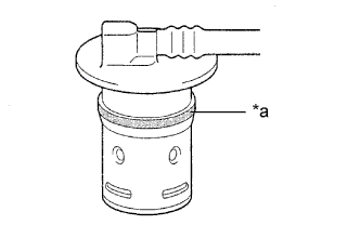
Text in Illustration *a Apply gasoline around the fuel cut off valve Apply a light coat of gasoline or spindle oil around the 2 fuel cut off valves of a new fuel cut off with tube valve assembly as shown in the illustration, and carefully insert them into the fuel tank assembly.
Note
Be careful not to drop the fuel tank breather tube gaskets into the fuel tank assembly.
-
Check that the fuel cut off valves are fully inserted.
-
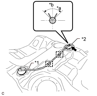
Text in Illustration *1 Fuel Cut Off with Tube Valve Assembly *2 Fuel Emission Hose *a 90° *b Up Engage the 2 clamps to connect the fuel cut off with tube valve assembly to the fuel tank assembly.
-
Connect the fuel emission hose to the fuel cut off with tube valve assembly and slide the clip to secure it.
Tech Tips
Engage the clip within the area shown in the illustration.
-
-
INSTALL NO. 3 FUEL TANK PROTECTOR
-
Slide the No. 3 fuel tank protector and engage the 2 claws to install it.
-
-
INSTALL NO. 2 FUEL TANK PROTECTOR
-

Slide the No. 2 fuel tank protector and engage the 2 claws to install it.
-
-
INSTALL NO. 2 FUEL TANK CUSHION
-
Install 7 new No. 2 fuel tank cushions to the fuel tank assembly.
-
-
INSTALL NO. 1 FUEL TANK CUSHION
-
Install a new No. 1 fuel tank cushion to the fuel tank assembly.
-
-
INSTALL FUEL TANK ASSEMBLY
-
Install the 4 clip nuts to the fuel tank assembly.
-
Text in Illustration *1 Pin *2 Fuel Tank Band Install the 2 fuel tank bands with the 2 pins as shown in the illustration.
-
Set the fuel tank assembly on an engine lifter with attachments.
Tech Tips
Using height adjustment attachments and plate lift attachments, keep the fuel tank assembly horizontal.
-
Using the engine lifter, slowly raise the fuel tank assembly, and then install the fuel tank assembly with the 2 bolts and 2 fuel tank bands.
- Torque:
- 45 N*m { 459 kgf*cm, 33 ft.*lbf }
Note
-
Be careful not to drop the fuel tank assembly.
-
When installing the fuel tank assembly, tilt it slightly to prevent it from interfering with the surrounding parts.
-
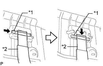
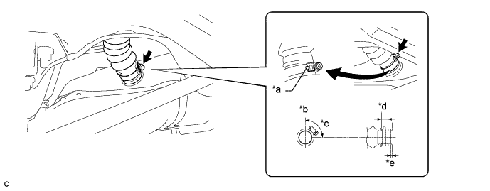
Connect the breather tube fuel hose to the fuel tank assembly and tighten the clamp to secure it.
Text in Illustration *a Claw *b Up *c 135° (Clamp Area) *d 2 to 7 mm (0.0787 to 0.276 in.) *e 0 to 3 mm (0 to 0.118 in.) - - Tech Tips
Make sure the bolt of the clamp is positioned within the area shown in the illustration.
-
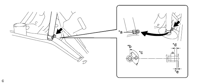
Connect the fuel tank to filler pipe hose to the fuel tank assembly and tighten the clamp to secure it.
Text in Illustration *a Claw *b Up *c 90° (Clamp Area) *d 17.5 mm (0.689 in.) *e 0 to 3 mm (0 to 0.118 in.) - - Tech Tips
Make sure the bolt of the clamp is positioned within the area shown in the illustration.
-
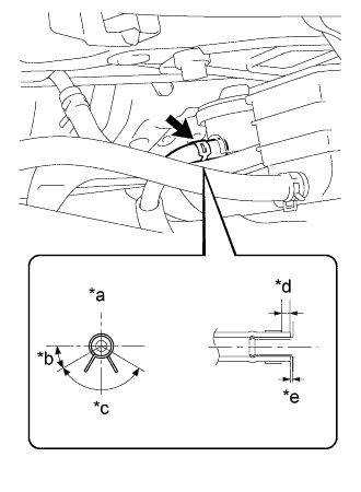
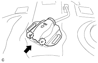
Text in Illustration *a Up *b 30° *c 120° (Clip Area) *d 2 to 7 mm (0.0787 to 0.276 in.) *e 0 to 3 mm (0 to 0.118 in.) Connect the fuel emission hose to the charcoal canister assembly and slide the clip to secure it.
Tech Tips
Engage the clip within the area shown in the illustration.
-
-
CONNECT FUEL PUMP TUBE SUB-ASSEMBLY
Note
Check that there is no damage or foreign matter on the connecting parts of the fuel lines.
-
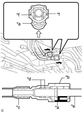
Text in Illustration *a Retainer *b Fuel Tube Connector *c Nylon Tube *d O-ring *e Fuel Pipe *f Claw 
Push 
Push in Connect the fuel pump tube sub-assembly.
-
Align the fuel tube connector with the fuel pipe, and push them together until the fuel tube connector makes a "click" sound. If it is difficult to push the fuel pipe into the fuel tube connector, apply a small amount of clean engine oil to the tip of the fuel pipe and reinsert it.
-
Connect the fuel lines and push in the retainer to engage the 2 claws. Check that the fuel pipe and fuel tube connector are securely connected by pulling on them.
-
-
-
INSTALL LOWER CENTER FUEL TANK PROTECTOR
-
Install the lower center fuel tank protector with the 4 bolts.
- Torque:
- 5.4 N*m { 55 kgf*cm, 48 in.*lbf }
-
-
INSTALL REAR NO. 1 STABILIZER BAR BRACKET
-
Install the 2 rear No. 1 stabilizer bar brackets with the 4 bolts.
- Torque:
- 31 N*m { 316 kgf*cm, 23 ft.*lbf }
-
-
INSTALL NO. 3 PARKING BRAKE CABLE ASSEMBLY
-
Install the No. 3 parking brake cable assembly with the bolt and nut.
- Torque:
- 6.0 N*m { 61 kgf*cm, 53 in.*lbf }
-
-
INSTALL NO. 2 PARKING BRAKE CABLE ASSEMBLY
-
Install the No. 2 parking brake cable assembly with the bolt and nut.
- Torque:
- 6.0 N*m { 61 kgf*cm, 53 in.*lbf }
-
-
INSTALL NO. 2 FLOOR UNDER COVER
-
for TMC Made:
-
Install the No. 2 floor under cover with the 6 nuts.
Tech Tips
The 6 nuts are attached to the No. 2 floor under cover.
- Torque:
- 4.0 N*m { 41 kgf*cm, 35 in.*lbf }
-
Install the screw and 2 clips.
-
-
for TMMR Made:
-
Install the No. 2 floor under cover with the 6 nuts.
Tech Tips
The 6 nuts are attached to the No. 2 floor under cover.
- Torque:
- 4.0 N*m { 41 kgf*cm, 35 in.*lbf }
-
Install the 2 clips.
-
-
-
INSTALL NO. 1 FLOOR UNDER COVER
-
for TMC Made:
-
Install the No. 1 floor under cover with the 5 nuts and 2 clips.
Tech Tips
The 5 nuts and 2 clips are attached to the No. 1 floor under cover.
- Torque:
- Nut
- 4.0 N*m { 41 kgf*cm, 35 in.*lbf }
-
Install the screw.
-
-
for TMMR Made:
-
Install the No. 1 floor under cover with the 5 nuts and 2 clips.
Tech Tips
The 5 nuts and 2 clips are attached to the No. 1 floor under cover.
- Torque:
- Nut
- 4.0 N*m { 41 kgf*cm, 35 in.*lbf }
-
-
-
INSTALL CENTER EXHAUST PIPE ASSEMBLY
-
INSTALL FUEL SUCTION TUBE WITH PUMP AND GAUGE ASSEMBLY
-
ADD FUEL