FUEL PUMP (for High Pressure) INSTALLATION
-
TEMPORARILY INSTALL FUEL PUMP WITH SEAL SUB-ASSEMBLY
-
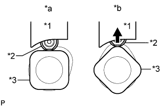
Text in Illustration *1 Fuel Pump Lifter Guide *2 Fuel Pump Lifter Assembly *3 Camshaft *a Correct *b Incorrect Turn the crankshaft pulley until the flat of the camshaft faces the fuel pump with seal sub- assembly installation hole of the cylinder head cover sub-assembly.
Tech Tips
This prevent the camshaft nose from pushing up the fuel pump lifter assembly when installing the fuel pump with seal sub-assembly.
-
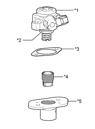
Text in Illustration *1 Fuel Pump with Seal Sub-assembly *2 O-ring *3 Fuel Pump Insulator *4 Fuel Pump Lifter Assembly *5 Fuel Pump Lifter Guide 
Engine Oil Application Area Apply engine oil to a new O-ring and install it to the fuel pump sub-assembly.
-
Apply engine oil to the inside of the fuel pump lifter guide and the outside of the fuel pump lifter assembly.
-
Install the fuel pump lifter assembly to the fuel pump lifter guide.
-
Install the fuel pump insulator to the fuel pump lifter guide.
-
Install the fuel pump with seal sub-assembly to the fuel pump lifter guide.
-
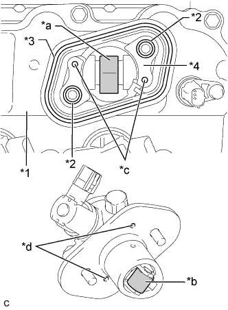
Text in Illustration *1 Cylinder Head Cover Sub-assembly *2 O-ring *3 Fuel Pump Spacer Gasket *4 No. 4 Camshaft Bearing Cap *a Pump Drive Cam (Engine Oil Application Area) *b Pump Lifter (Engine Oil Application Area) *c Knock Pin *d Pin Hole Apply 30 cc (1.8 cu. in.) of engine oil to the pump drive cam.
-
Apply engine oil to the fuel pump lifter assembly.
-
Apply engine oil to 2 new O-rings and install them to the No. 4 camshaft bearing cap.
-
Install a new fuel pump spacer gasket to the cylinder head cover sub-assembly.
-
Set the fuel pump with seal sub-assembly on the cylinder head cover sub-assembly.
-
Temporarily install the fuel pump with seal sub-assembly with the 2 bolts, leaving some allowance for left and right movement.
-
-
TEMPORARILY INSTALL NO. 1 FUEL PIPE SUB-ASSEMBLY
-
Connect the No. 1 fuel pipe sub-assembly to the fuel delivery pipe sub-assembly and tighten the union nut by hand.
-
Connect the No. 1 fuel pipe sub-assembly to the fuel pump with seal sub-assembly and tighten the union nut by hand.
Note
Do not damage the seals of the union nuts of the No. 1 fuel pipe sub-assembly when installing.
-
-
INSTALL FUEL PUMP WITH SEAL SUB-ASSEMBLY
Tech Tips
Perform "Inspection After Repair" after replacing the fuel pump with seal sub-assembly Click here.
-
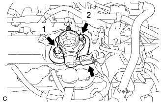
Tighten the 2 bolts in the order shown in the illustration.
- Torque:
- 30 N*m { 306 kgf*cm, 22 ft.*lbf }
-
Connect the fuel pump with seal sub-assembly connector.
-
-
INSTALL NO. 1 FUEL PIPE SUB-ASSEMBLY
-
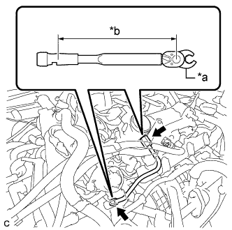
Text in Illustration *a 17 mm Union Nut Wrench *b Torque Wrench Fulcrum Length Using a 17 mm union nut wrench, tighten the union nuts on the fuel pump with seal sub-assembly side of the No. 1 fuel pipe sub-assembly.
- Torque:
- 35 N*m { 357 kgf*cm, 26 ft.*lbf }
Tech Tips
-
Calculate the torque wrench reading when changing the fulcrum length of the torque wrench Click here.
-
When using a 17 mm union nut wrench (fulcrum length of 30 mm (1.18 in.)) + torque wrench (fulcrum length of 180 mm (7.09 in.)): 30 N*m (306 kgf*cm, 22 ft.*lbf)
-
Using a 17 mm union nut wrench, tighten the union nuts on the fuel delivery pipe sub-assembly side of the No. 1 fuel pipe sub-assembly.
- Torque:
- 35 N*m { 357 kgf*cm, 26 ft.*lbf }
Tech Tips
-
Calculate the torque wrench reading when changing the fulcrum length of the torque wrench Click here.
-
When using a 17 mm union nut wrench (fulcrum length of 30 mm (1.18 in.)) + torque wrench (fulcrum length of 180 mm (7.09 in.)): 30 N*m (306 kgf*cm, 22 ft.*lbf)
-
-
INSTALL NO. 1 FUEL PIPE
-
Install the No. 1 fuel pipe and a new gasket to the fuel pump with seal sub-assembly.
- Torque:
- 40 N*m { 408 kgf*cm, 30 ft.*lbf }
-
-
CONNECT FUEL TUBE SUB-ASSEMBLY
Note
Check that there is no damage or foreign matter on the connecting parts of the fuel lines.
-
Connect the fuel tube sub-assembly to the No. 1 fuel pipe.
-
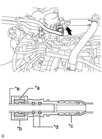
Text in Illustration *a Retainer *b Fuel Tube Connector *c Nylon Tube *d O-ring *e Fuel Pipe 
Push Align the fuel tube connector with the fuel pipe, and push them together until the fuel tube connector makes a "click" sound. If it is difficult to push the fuel pipe into the fuel tube connector, apply a small amount of clean engine oil to the tip of the fuel pipe and reinsert it.
-
After connecting the fuel pipes, check that the fuel pipe and fuel tube connector are securely connected by pulling on them.
-
Push in the fuel tube connector cover.
-
-
-
INSTALL FUEL PUMP PROTECTOR
-
Install the fuel pump protector to the cylinder head cover sub-assembly with the 2 bolts.
- Torque:
- 21 N*m { 214 kgf*cm, 15 ft.*lbf }
-
-
INSTALL AIR CLEANER CASE SUB-ASSEMBLY
-
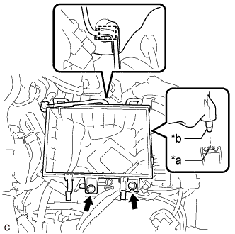
Text in Illustration *a Hole *b Projection Insert the projection of the air cleaner case sub-assembly into the hole of the No. 1 air cleaner bracket as shown in the illustration.
-
Install the 2 bolts.
- Torque:
- 5.0 N*m { 51 kgf*cm, 44 in.*lbf }
-
Connect the wire harness clamp.
-
-
INSTALL AIR CLEANER FILTER ELEMENT SUB-ASSEMBLY
-
Install the air cleaner filter element sub-assembly to the air cleaner case sub-assembly.
Note
Install the air cleaner filter element sub-assembly with the printed side facing the vehicle left.
-
-
INSTALL INLET AIR CLEANER ASSEMBLY
-
Install the inlet air cleaner assembly with the 2 bolts.
- Torque:
- 8.0 N*m { 82 kgf*cm, 71 in.*lbf }
-
-
INSTALL COOL AIR INTAKE DUCT SEAL
-
Install the cool air intake duct seal with the 9 clips.
-
-
INSTALL THROTTLE BODY WITH MOTOR ASSEMBLY
-
CONNECT CABLE TO NEGATIVE BATTERY TERMINAL
CAUTION:
When disconnecting the cable, some systems need to be initialized after the cable is reconnected Click here.
-
INSPECT FOR FUEL LEAK
-
Check fuel pump operation.
-
Connect the GTS to the DLC3.
-
Turn the engine switch to on (IG).
Note
Do not start the engine.
-
Turn the GTS on.
-
Enter the following menus: Powertrain / Engine / Active Test / Activate the Circuit Relay.
-
Check for pressure in the fuel tube sub-assembly from the fuel line. Check that sounds of fuel flowing from the fuel tank assembly can be heard. If no sounds can be heard, check the integration relay, fuel pump, ECM and wiring connectors.
-
-
Inspect for fuel leaks.
-
Check that there are no fuel leaks from the fuel system after doing any maintenance or repairs. If there is a fuel leak, repair or replace parts as necessary.
-
-
Turn the engine switch off.
-
Disconnect the GTS from the DLC3.
-
-
PERFORM INITIALIZATION
-
Perform "Inspection After Repair" after replacing the fuel pump with seal sub-assembly Click here.
-