ENGINE ASSEMBLY REMOVAL

-
PRECAUTION
CAUTION:
The engine assembly with transaxle is very heavy. Be sure to follow the procedure described in the repair manual, or the engine lifter may suddenly drop.
Note
After turning the engine switch off, waiting time may be required before disconnecting the cable from the negative (-) battery terminal. Therefore, make sure to read the disconnecting the cable from the negative (-) battery terminal notices before proceeding with work Click here.
-
RECOVER REFRIGERANT FROM AIR CONDITIONING SYSTEM
-
Turn the A/C switch on.
-
Operate the air conditioning with a set temperature of 25°C (77°F) and the blower at low for 10 minutes to circulate the refrigerant. This causes most of the compressor oil from the various components of the air conditioning system to collect in the air conditioning compressor.
-
Turn the ignition switch off.
-
Recover the refrigerant from the air conditioning system using a refrigerant recovery unit.
-
-
DISCHARGE FUEL SYSTEM PRESSURE
-
ALIGN FRONT WHEELS FACING STRAIGHT AHEAD
-
SECURE STEERING WHEEL
-
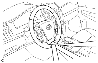
Secure the steering wheel with the seat belt in order to prevent rotation.
Tech Tips
This operation is useful to prevent damage to the spiral cable.
-
-
REMOVE FRONT WHEELS
-
DISCONNECT CABLE FROM NEGATIVE BATTERY TERMINAL
Note
When disconnecting the cable, some systems need to be initialized after the cable is reconnected Click here.
-
REMOVE FRONT WHEEL OPENING EXTENSION PAD RH
-
Remove the 3 screws and front wheel opening extension pad RH.
-
-
REMOVE ENGINE UNDER COVER RH
-
Remove the 3 screws, 3 clips and engine under cover RH.
-
-
REMOVE FRONT WHEEL OPENING EXTENSION PAD LH
-
Remove the 3 screws and front wheel opening extension pad LH.
-
-
REMOVE ENGINE UNDER COVER LH
-
Remove the 3 screws, 2 clips and engine under cover LH.
-
-
REMOVE FRONT FENDER APRON SEAL LH
-
Remove the 2 bolts, clip and front fender apron seal LH.
-
-
REMOVE FRONT FENDER APRON SEAL RH
-
Remove the 2 bolts, clip and front fender apron seal RH.
-
-
DRAIN ENGINE OIL
-
Remove the oil filler cap sub-assembly.
-
Remove the oil pan drain plug and gasket, and drain the engine oil into a container.
-
Clean the oil pan drain plug.
-
Install a new gasket to the oil pan drain plug.
-
Install the oil pan drain plug.
- Torque:
- 40 N*m { 408 kgf*cm, 30 ft.*lbf }
-
-
DRAIN ENGINE COOLANT
CAUTION:
Do not remove the radiator cap sub-assembly or radiator drain cock plug while the engine and radiator assembly are still hot. Pressurized, hot engine coolant and steam may be released and cause serious burns.
-
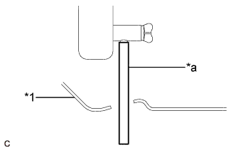
Text in Illustration *1 Engine Under Cover LH *a Hose Connect a hose with an inside diameter of 9 mm (0.354 in.) to the radiator drain cock as shown in the illustration.
-
Loosen the radiator drain cock plug.
-
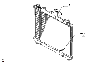
Text in Illustration *1 Radiator Cap Sub-assembly *2 Radiator Drain Cock Plug Remove the radiator cap sub-assembly. Then drain the engine coolant.
Tech Tips
Collect the engine coolant in a container and dispose of it according to the regulations in your area.
-
Disconnect the hose from the radiator drain cock.
-
-
DRAIN AUTOMATIC TRANSAXLE FLUID
-
Remove the refill plug and gasket from the rear transaxle cover sub-assembly.
-
Using a 6 mm hexagon socket wrench, remove the overflow plug and gasket from the automatic transaxle oil pan sub-assembly.
-
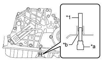
Text in Illustration *1 No. 1 Transmission Oil Filler Tube *a 6 mm Hexagon Socket Wrench *b Overflow Plug Hole Using a 6 mm hexagon socket wrench, remove the No. 1 transmission oil filler tube from the automatic transaxle oil pan sub-assembly.
-
Drain automatic transaxle fluid from the automatic transaxle assembly.
-
Text in Illustration *1 No. 1 Transmission Oil Filler Tube *a 6 mm Hexagon Socket Wrench *b Overflow Plug Hole Using a 6 mm hexagon socket wrench, install the No. 1 transmission oil filler tube to the automatic transaxle oil pan sub-assembly.
- Torque:
- 0.8 N*m { 8 kgf*cm, 7 in.*lbf }
-
Using a 6 mm hexagon socket wrench, temporarily install the gasket and overflow plug to the automatic transaxle oil pan sub-assembly.
Tech Tips
Reuse the old gasket as the overflow plug will be removed again to adjust the fluid level.
-
Temporarily install the gasket and refill plug to the automatic transaxle assembly.
Tech Tips
Reuse the old gasket as the refill plug will be removed again to adjust the fluid level.
-
-
REMOVE COOL AIR INTAKE DUCT SEAL
-
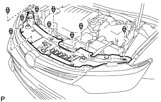
Remove the 9 clips and cool air intake duct seal.
-
-
REMOVE NO. 1 ENGINE COVER SUB-ASSEMBLY
-
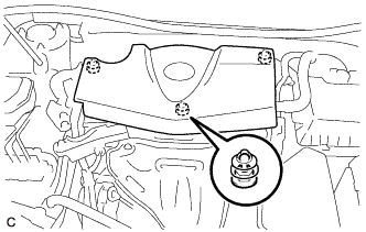
Disengage the 3 grommets to remove the No. 1 engine cover sub-assembly.
Note
When removing the No. 1 engine cover sub-assembly, make sure to lift it upward. Pulling the No. 1 engine cover sub-assembly towards you may damage the No. 1 engine cover sub-assembly.
-
-
REMOVE INLET AIR CLEANER ASSEMBLY
-
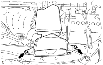
Remove the 2 bolts and inlet air cleaner assembly.
-
-
REMOVE BATTERY
-
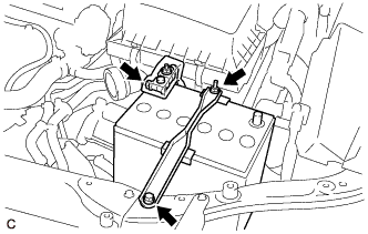
Loosen the nut, and disconnect the cable from the positive (+) battery terminal.
-
Loosen the nut, and remove the bolt and battery clamp.
-
Remove the battery and battery tray.
-
-
REMOVE AIR CLEANER CAP WITH AIR CLEANER HOSE
-
Slide the clip and disconnect the ventilation hose from the cylinder head cover sub-assembly.
-
Disengage the ventilation hose clamp.
-
Disconnect the mass air flow meter sub-assembly connector.
-
Disengage the wire harness clamp.
-
Disconnect the union to connector tube hose from the air cleaner hose sub-assembly.
-
Disengage the 2 air cleaner cap clamps and 2 guides.
-
Loosen the hose clamp and remove the air cleaner cap with air cleaner hose from the throttle body with motor assembly.
-
-
REMOVE AIR CLEANER FILTER ELEMENT SUB-ASSEMBLY
-
Remove the air cleaner filter element sub-assembly from the air cleaner case sub-assembly.
-
-
REMOVE AIR CLEANER CASE SUB-ASSEMBLY
-
Disconnect the wire harness clamp.
-
Remove the 2 bolts and air cleaner case sub-assembly.
-
-
DISCONNECT NO. 1 RADIATOR HOSE
-
Slide the clip and disconnect the No. 1 radiator hose from the cylinder head sub-assembly.
-
-
DISCONNECT NO. 2 RADIATOR HOSE
-
Slide the clip and disconnect the No. 2 radiator hose from the water inlet.
-
-
DISCONNECT HEATER INLET WATER HOSE
-
Disengage the clamp to separate the heater inlet water hose.
-
Slide the clip and disconnect the heater inlet water hose from the cylinder head sub-assembly.
-
-
DISCONNECT HEATER OUTLET WATER HOSE
-
Slide the clip and disconnect the heater outlet water hose from the EGR cooler assembly.
-
-
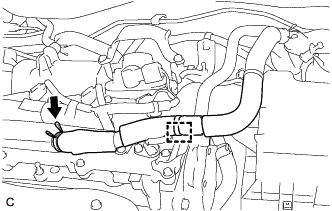
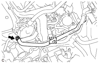
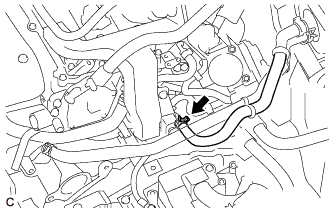
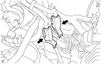
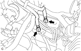
DISCONNECT INLET NO. 1 OIL COOLER HOSE
-
Slide the clip and disconnect the inlet No. 1 oil cooler hose from the automatic transaxle assembly.
-
-
DISCONNECT OUTLET NO. 1 OIL COOLER HOSE
-
Slide the clip and disconnect the outlet No. 1 oil cooler hose from the automatic transaxle assembly.
-
-
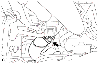
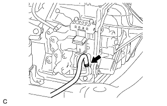
REMOVE STARTER ASSEMBLY
-
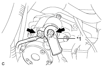
Text in Illustration *1 Terminal Cap Open the terminal cap.
-
Remove the nut and disconnect terminal 30.
-
Disconnect the starter assembly connector.
-
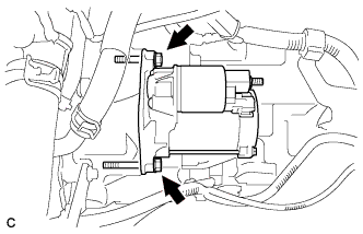
Remove the 2 bolts and starter assembly.
-
-
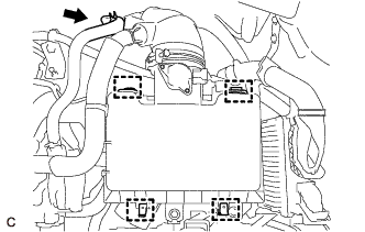
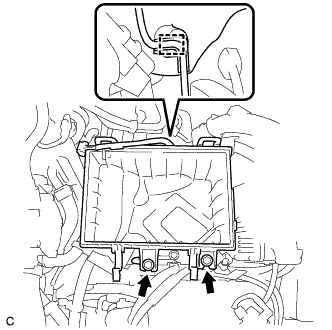
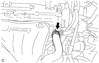
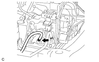
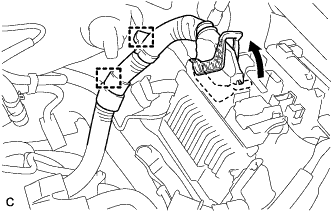
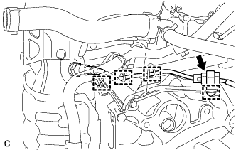
DISCONNECT ENGINE WIRE
-
Remove the No. 1 relay block cover from the engine room relay block assembly.
-
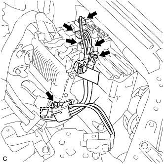
Remove the bolt and separate the engine wire.
-
Disengage the wire harness clamp.
-
Disconnect the 4 connectors from the engine room relay block assembly.
-
Remove the nut from the engine room relay block assembly.
-
Using a screwdriver, disengage the claw and separate the engine wire from the engine room relay block assembly.
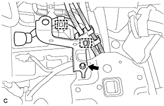
-
Pull up the lock lever while pushing the lock on the lever to disconnect the ECM connector.
Note
After disconnecting the ECM connector, make sure that dirt, water or other foreign matter does not contact the connecting part of the ECM connector.
-
Disengage the 2 wire harness clamps.
-
-
REMOVE NO. 1 AIR CLEANER BRACKET
-
Disconnect the 2 wire harness clamps.
-
Remove the bolt and No. 1 air cleaner bracket from the battery carrier.
-
-
DISCONNECT TRANSMISSION CONTROL CABLE ASSEMBLY
-
Move the shift lever to N.
-
Remove the clip and disconnect the transmission control cable assembly from the No. 1 transmission control cable bracket.
-
Remove the nut and disconnect the transmission control cable assembly from the transmission control shaft lever.
-
-
REMOVE EARTH WIRE
-
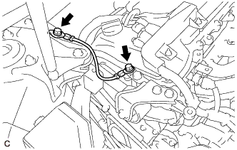
Remove the 2 bolts and earth wire.
-
-
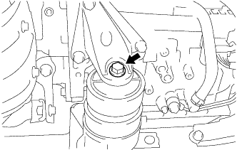
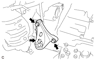
REMOVE NO. 2 ENGINE MOUNTING STAY RH
-
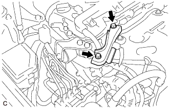
Remove the 2 bolts and No. 2 engine mounting stay RH.
-
-
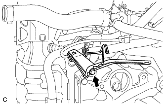
REMOVE ENGINE MOVING CONTROL ROD BRACKET
-
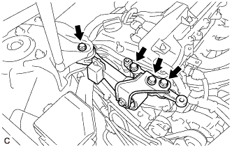
Remove the 4 bolts and engine moving control rod bracket.
-
-
REMOVE ENGINE MOVING CONTROL ROD
Tech Tips
Perform this procedure only when replacement of the engine moving control rod is necessary.
-
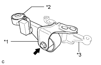
Text in Illustration *1 No. 3 Engine Mounting Stay RH *2 Engine Moving Control Rod *3 Engine Moving Control Rod Bracket Remove the bolt, No. 3 engine mounting stay RH and engine moving control rod from the engine moving control rod bracket.
-
-
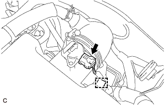
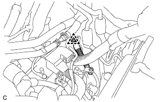
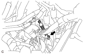
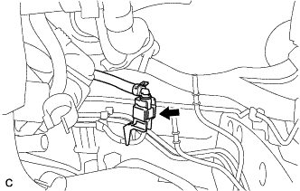
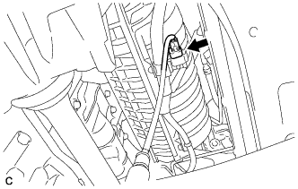
DISCONNECT UNION TO CHECK VALVE HOSE
-
Slide the clip and disconnect the union to check valve hose from the vacuum pump assembly.
-
-
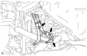
DISCONNECT NO. 1 COOLER REFRIGERANT DISCHARGE HOSE
-
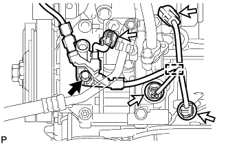
Remove the bolt.
-
Disconnect each connector.
-
Disengage the clamp to disconnect the wire harness.
-
Remove the bolt and disconnect the No. 1 cooler refrigerant discharge hose from the compressor assembly with pulley.
-
Remove the O-ring from the No. 1 cooler refrigerant discharge hose.
Note
Seal the openings of the disconnected parts using vinyl tape to prevent entry of moisture and foreign matter.
-
-
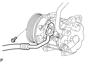
DISCONNECT NO. 1 COOLER REFRIGERANT SUCTION HOSE
-
Remove the bolt and disconnect the No. 1 cooler refrigerant suction hose from the compressor assembly with pulley.
-
Remove the O-ring from the No. 1 cooler refrigerant suction hose.
Note
Seal the openings of the disconnected parts using vinyl tape to prevent entry of moisture and foreign matter.
-
-
DISCONNECT FUEL TUBE SUB-ASSEMBLY
-
Remove the 2 EFI fuel pipe clamps Click here.
-
Disconnect the 2 fuel tube sub-assemblies from the 2 fuel tubes Click here.
-
-
DISCONNECT FUEL VAPOR FEED HOSE ASSEMBLY
-
Remove the EFI fuel pipe clamp.
-
Disconnect the fuel vapor feed hose assembly from the floor tube Click here.
-
-
REMOVE FRONT EXHAUST PIPE ASSEMBLY (TWC: Rear Catalyst)
-
Disconnect the heated oxygen sensor connector.
-
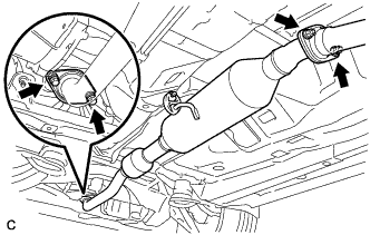
Remove the 2 bolts, 2 compression springs, 2 nuts and front exhaust pipe assembly (TWC: Rear Catalyst) from the exhaust manifold converter sub-assembly (TWC: Front Catalyst) and center exhaust pipe assembly.
-
Disconnect the front exhaust pipe assembly (TWC: Rear Catalyst) from the exhaust pipe support.
-
Remove the 2 exhaust pipe gaskets from the exhaust manifold converter sub-assembly (TWC: Front Catalyst) and front exhaust pipe assembly (TWC: Rear Catalyst).
-
-
REMOVE FRONT DRIVE SHAFT ASSEMBLY
-
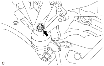
SEPARATE STEERING INTERMEDIATE SHAFT ASSEMBLY
-
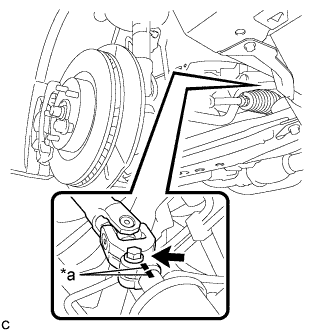
Text in Illustration *a Matchmark Put matchmarks on the steering intermediate shaft assembly and steering link assembly.
-
Remove the bolt.
-
Separate the steering intermediate shaft assembly from the steering link assembly.
-
-
REMOVE FLYWHEEL HOUSING UNDER COVER
-
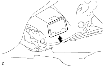
Remove the flywheel housing under cover.
-
-
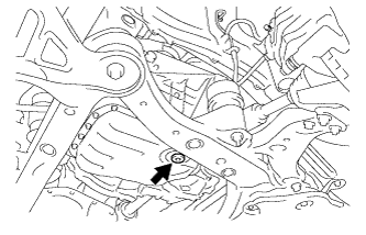
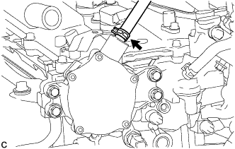
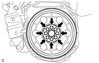
REMOVE DRIVE PLATE AND TORQUE CONVERTER ASSEMBLY SETTING BOLT
-
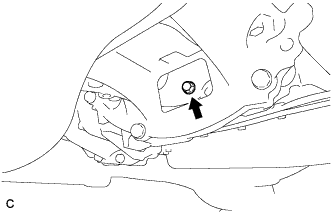
Turn the crankshaft to gain access to the removable locations of the 6 drive plate and torque converter assembly setting bolts and remove each drive plate and torque converter assembly setting bolt while holding the crankshaft pulley bolt with a wrench.
Tech Tips
There will be one black colored drive plate and torque converter assembly setting bolt.
-
-
REMOVE ENGINE ASSEMBLY WITH TRANSAXLE
-
Place height adjustment attachments and plate lift attachments in the positions shown in the illustration and set an engine lifter underneath the engine assembly with transaxle.
Text in Illustration 
Attachment Installation Position Note
-
Using height adjustment attachments and plate lift attachments, place the engine assembly with transaxle horizontally.
-
Securely support the engine assembly to prevent it from turning upside down until it is secured to an engine stand.
-
To prevent the oil pan sub-assembly from deforming, do not place any attachments under the oil pan sub-assembly of the engine assembly with transaxle.
-
Do not perform any procedures while the engine assembly is suspended because doing so may cause the engine assembly to drop, resulting in injury. However, the engine assembly needs to be suspended when it is installed to or removed from an engine stand.
-
-
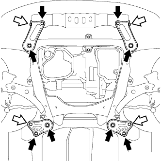
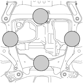
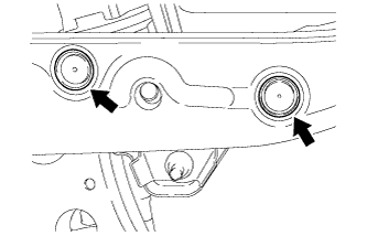
Remove the 4 bolts, 2 nuts, frame side rail plate sub-assembly RH and frame side rail plate sub-assembly LH.
Text in Illustration 
Bolt 
Nut -
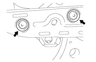
Remove the 4 bolts, 2 nuts, front suspension member bracket sub-assembly RH and front suspension member bracket sub-assembly LH.
-
Operate the engine lifter and remove the engine assembly with transaxle from the vehicle.
Note
-
Make sure that the engine assembly with transaxle is clear of all wiring and hoses.
-
While lowering the engine assembly with transaxle from the vehicle, do not allow it to contact the vehicle.
-
-
-
INSTALL ENGINE HANGERS
-
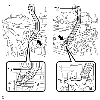
Text in Illustration *1 No. 1 Engine Hanger *2 No. 2 Engine Hanger *a Stopper *b Rib Install the No. 1 engine hanger with the bolt as shown in the illustration.
- Torque:
- 43 N*m { 438 kgf*cm, 32 ft.*lbf }
Note
Make sure to install the No. 1 engine hanger with the stopper contacting the rib of the cylinder head sub-assembly as shown in the illustration.
Tech Tips
Item Part No. No. 1 Engine Hanger 12281-0V010 No. 2 Engine Hanger 12282-0V010 Bolt 90105-C0170 -
Install the No. 2 engine hanger with the bolt as shown in the illustration.
- Torque:
- 43 N*m { 438 kgf*cm, 32 ft.*lbf }
Note
Make sure to install the No. 2 engine hanger with the stopper positioned between the ribs of the cylinder head sub-assembly as shown in the illustration.
-
Using an engine sling device and engine lift, secure the engine assembly with transaxle.
Note
-
Adjust the angle of the sling device carefully to prevent the engine assembly or engine hangers from deforming or becoming damaged.
-
Do not perform any procedures while the engine assembly is suspended because doing so may cause the engine assembly to drop, resulting in injury. However, the engine assembly needs to be suspended when it is installed to or removed from an engine stand.
-
-
-
REMOVE ENGINE WIRE
-
Remove the engine wire from the engine assembly with transaxle.
-
-
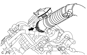
REMOVE V-RIBBED BELT
-
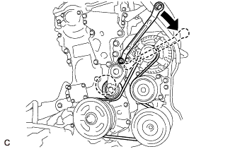
Attach a wrench to the hexagonal portion of the V- ribbed belt tensioner assembly as shown in the illustration, rotate the V-ribbed belt tensioner assembly clockwise, and remove the V-ribbed belt.
-
-
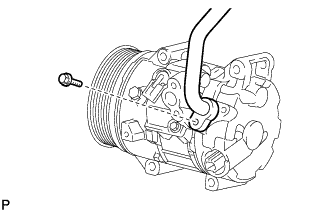
REMOVE COMPRESSOR ASSEMBLY WITH PULLEY
-
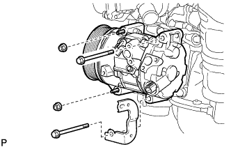
Remove the 2 bolts and 2 nuts, and bracket.
-
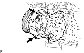
Using an E8 "TORX" socket wrench, remove the 2 stud bolts and compressor assembly with pulley.
Tech Tips
Remove the compressor assembly with pulley from the vehicle with the stud bolts remaining in the compressor assembly with pulley.
-
-
REMOVE GENERATOR ASSEMBLY
-
Disconnect the generator assembly connector.
-
Open the terminal cap.
-
Remove the nut and disconnect the wire harness from terminal B.
-
Remove the bolt and wire harness clamp bracket from the generator assembly.
-
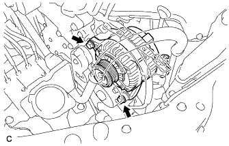
Remove the 2 bolts and generator assembly.
-
-
REMOVE FRONT FRAME ASSEMBLY
-
Remove the nut and separate the engine mounting insulator LH.
-
Remove the bolt and separate the front engine mounting insulator.
-
Remove the nut and separate the engine mounting insulator RH.
-
Remove the front frame assembly.
-
Using height adjustment attachments and plate lift attachments, place the engine assembly with transaxle on a flat level surface.
Note
-
Using height adjustment attachments and plate lift attachments, place the engine assembly with transaxle horizontally.
-
To prevent the oil pan sub-assembly from deforming, do not place any attachments under the oil pan sub-assembly of the engine assembly with transaxle.
-
-
-
REMOVE FRONT ENGINE MOUNTING INSULATOR
Tech Tips
Perform this procedure only when replacement of the front engine mounting insulator is necessary.
-
Remove the 3 nuts and front engine mounting insulator.
-
-
REMOVE ENGINE MOUNTING INSULATOR LH
Tech Tips
Perform this procedure only when replacement of the engine mounting insulator LH is necessary.
-
Remove the 2 hole plugs from the front frame assembly.
-
Remove the 3 nuts and engine mounting insulator LH.
-
-
REMOVE ENGINE MOUNTING INSULATOR RH
Tech Tips
Perform this procedure only when replacement of the engine mounting insulator RH is necessary.
-
Remove the 2 hole plugs from the front frame assembly.
-
Remove the 3 nuts and engine mounting insulator RH.
-
-
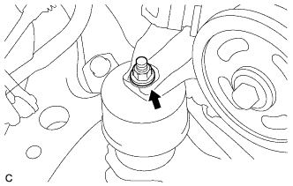
REMOVE DRIVE SHAFT BEARING BRACKET
-
Remove the 3 bolts and drive shaft bearing bracket.
-
-
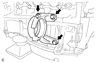
REMOVE ENGINE MOUNTING BRACKET RH
-
Remove the 3 bolts and engine mounting bracket RH.
-
-
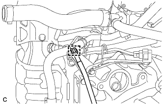
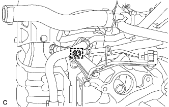
REMOVE WIRE HARNESS CLAMP BRACKET
-
Disconnect the transmission breather hose sub-assembly from the clamp.
-
Remove the clamp from the wire harness clamp bracket.
-
Disconnect the oxygen sensor connector.
-
Disengage the 4 clamps to disconnect the wire harness from the wire harness clamp bracket.
-
Remove the bolt and wire harness clamp bracket from the transaxle housing.
-
-
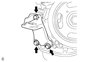
REMOVE FRONT ENGINE MOUNTING BRACKET
-
Remove the 3 bolts and front engine mounting bracket from the transaxle housing.
-
-
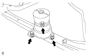
REMOVE AUTOMATIC TRANSAXLE ASSEMBLY
-
Support the automatic transaxle assembly with a transmission jack.
Note
-
In order to protect the automatic transaxle oil pan sub-assembly, place attachments on the transmission jack.
-
Make sure that the attachments and automatic transaxle oil pan sub-assembly are centered on the transmission jack.
-
To prevent the automatic transaxle oil pan sub-assembly from being deformed, do not place any attachments under the automatic transaxle oil pan sub-assembly.
-
Hold the engine assembly with a suitable adapter, such as a rope, during the operation.
-
-
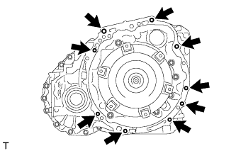
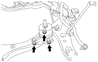
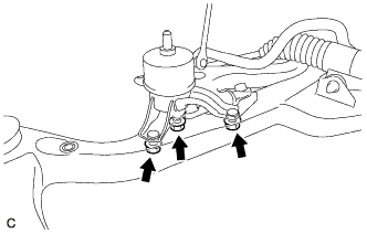
Remove the 9 bolts and automatic transaxle assembly from the engine assembly.
Note
-
Secure the automatic transaxle assembly to the transmission jack using a belt, etc. to prevent it from falling.
-
To prevent damage to the knock pins, do not pry between the automatic transaxle assembly and engine assembly.
-
-
-
REMOVE DRIVE PLATE AND RING GEAR SUB-ASSEMBLY
-
Using height adjustment attachments and plate lift attachments, place the engine assembly on a flat level surface.
Note
-
Using height adjustment attachments and plate lift attachments, place the engine assembly horizontally.
-
To prevent the oil pan sub-assembly from deforming, do not place any attachments under the oil pan sub-assembly of the engine assembly.
-
Using an engine sling device and engine lift, secure the engine assembly before service.
-
-
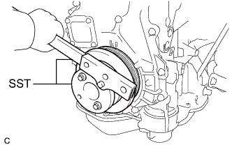
Using SST, hold the crankshaft pulley.
- SST
- 09213-54015
- 09330-00021
Tech Tips
Part number of installation bolt for SST (crankshaft pulley holding tool): 91551-80650 (quantity: 2)
-
Remove the 8 bolts, rear drive plate spacer, drive plate and ring gear sub-assembly and front drive plate spacer.
-
-
INSTALL ENGINE ASSEMBLY TO ENGINE STAND
-
Install the engine assembly to an engine stand.
Note
-
Adjust the angle of the sling device carefully to prevent the engine assembly or engine hangers from deforming or becoming damaged.
-
Do not perform any procedure while the engine assembly is suspended because doing so may cause the engine assembly to drop, resulting in injury. However, the engine assembly needs to be suspended when it is installed to or removed from an engine stand.
-
-
-
REMOVE ENGINE HANGERS
-
Remove the 2 bolts, No. 1 engine hanger and No. 2 engine hanger.
-