CAMSHAFT INSTALLATION

Tech Tips
Perform "Inspection After Repair" after replacing the camshaft, No. 2 camshaft, camshaft timing gear assembly or camshaft timing exhaust gear assembly Click here.
-
INSTALL NO. 2 CAMSHAFT BEARING
-
Clean the No. 2 camshaft bearing.
-
Install the No. 2 camshaft bearing to the camshaft housing sub-assembly.
-
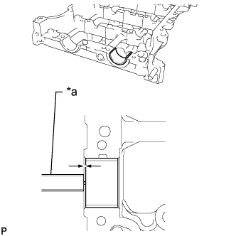
Text in Illustration *a Vernier Caliper Using a vernier caliper, measure the distance between the camshaft housing sub-assembly edge and the No. 2 camshaft bearing edge.
Standard Distance 1.15 to 1.85 mm (0.0453 to 0.0728 in.)
-
-
INSTALL NO. 1 CAMSHAFT BEARING
-
Text in Illustration *a Vernier Caliper Clean the No. 1 camshaft bearing.
-
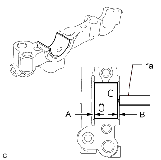
Install the No. 1 camshaft bearing to the No. 1 camshaft bearing cap.
-
Using a vernier caliper, measure the distance between the No. 1 camshaft bearing cap edge and the No. 1 camshaft bearing edge.
Difference Between (A) and (B) 0 to 0.7 mm (0 to 0.0276 in.)
-
-
INSTALL OIL CONTROL VALVE FILTER
-
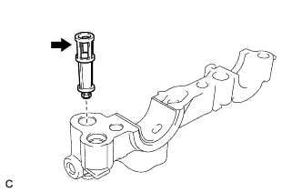
Install the oil control valve filter to the No. 1 camshaft bearing cap.
-
-
INSTALL CAMSHAFT TIMING EXHAUST GEAR ASSEMBLY
-
Secure the No. 2 camshaft in a vise by clamping the hexagonal part between aluminum plates.
Note
Do not damage the No. 2 camshaft by tightening the vise excessively.
-
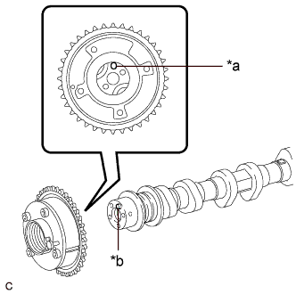
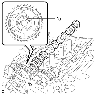
Text in Illustration *a Knock Pin Hole *b Knock Pin Align and fit the knock pin of the No. 2 camshaft with the knock pin hole of the camshaft timing exhaust gear assembly.
Note
Be careful not to damage the contact surface of the camshaft timing exhaust gear assembly with the knock pin of the No. 2 camshaft.
-
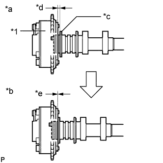
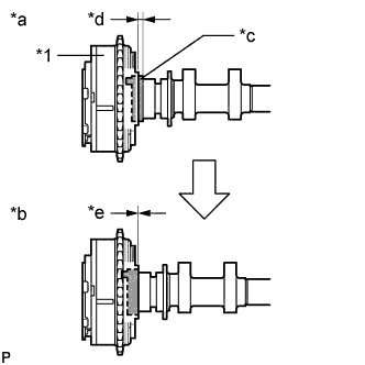
Text in Illustration *1 Camshaft Timing Exhaust Gear Assembly *a Incorrect *b Correct *c No. 2 Camshaft Flange *d Gap *e No Gap Check that there is no gap between the camshaft timing exhaust gear assembly and No. 2 camshaft flange.
-
Secure the camshaft timing exhaust gear assembly with the bolt.
- Torque:
- 85 N*m { 867 kgf*cm, 63 ft.*lbf }
Note
Do not disassemble the camshaft timing exhaust gear assembly.
Tech Tips
Perform "Inspection After Repair" after replacing the camshaft timing exhaust gear assembly Click here.
-
-
SET NO. 1 CYLINDER TO TDC/COMPRESSION
-
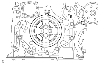
Text in Illustration *a Timing Notch (Groove) Turn the crankshaft pulley until its timing notch (groove) and the timing mark "0" of the timing chain cover sub-assembly are aligned.
-
-
INSTALL NO. 2 CAMSHAFT
-
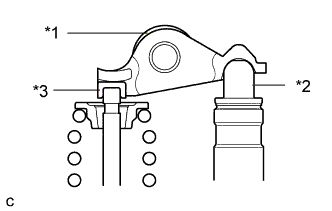
Text in Illustration *1 No. 1 Valve Rocker Arm Sub-assembly *2 Valve Lash Adjuster Assembly *3 Valve Stem Cap Make sure that the No. 1 valve rocker arm sub-assemblies are installed as shown in the illustration.
-
Clean the camshaft journals.
-
Apply a light coat of engine oil to the camshaft journals, camshaft housing sub-assembly and camshaft bearing caps.
-
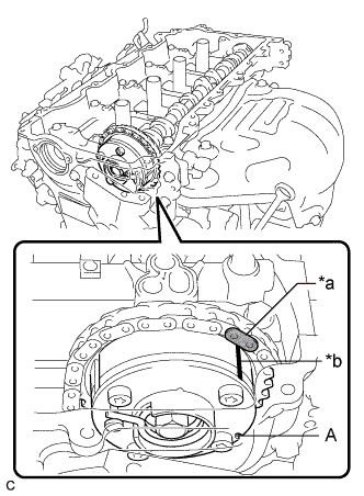
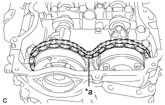
Text in Illustration *a Paint Mark *b Timing Mark Hold up the chain sub-assembly, align the timing mark and paint mark, and install the No. 2 camshaft to the camshaft housing sub-assembly.
Tech Tips
-
"A" is not a timing mark.
-
Perform "Inspection After Repair" after replacing the No. 2 camshaft Click here.
-
-
-
INSTALL CAMSHAFT TIMING GEAR ASSEMBLY
-
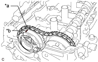
Text in Illustration *a Paint Mark *b Timing Mark Align the paint mark of the chain sub-assembly and the timing mark of the camshaft timing gear assembly. Then install the camshaft timing gear assembly.
Tech Tips
Perform "Inspection After Repair" after replacing the camshaft timing gear assembly Click here.
-
-
INSTALL CAMSHAFT
-
Text in Illustration *1 No. 1 Valve Rocker Arm Sub-assembly *2 Valve Lash Adjuster Assembly *3 Valve Stem Cap Make sure that the No. 1 valve rocker arm sub-assemblies are installed as shown in the illustration.
-
Clean the camshaft journals.
-
Apply a light coat of engine oil to the camshaft journals and camshaft housing sub-assembly.
-
Text in Illustration *a Knock Pin Hole *b Knock Pin Align and fit the knock pin of the camshaft with the knock pin hole of the camshaft timing gear assembly.
Note
Be careful not to damage the contact surface of the camshaft timing gear assembly with the knock pin of the camshaft.
-
Text in Illustration *1 Camshaft Timing Gear Assembly *a Incorrect *b Correct *c Portion (A) of Camshaft *d Gap *e No Gap Check that there is no gap between the camshaft timing gear assembly and portion (A) of the camshaft shown in the illustration.
Tech Tips
Perform "Inspection After Repair" after replacing the camshaft Click here.
-
-
TEMPORARILY INSTALL CAMSHAFT TIMING GEAR BOLT
Note
There are different types of camshaft timing gear bolts. Make sure to check the identification mark to determine the tightening torque.
Identification Mark Item Identification Mark Stamp Type A A Type B D 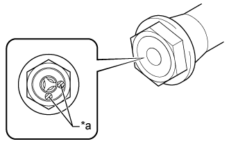
Text in Illustration *a Identification Mark Stamp
-
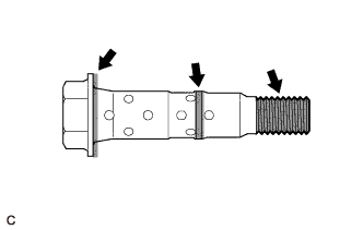
Apply engine oil to the areas of the camshaft timing gear bolt shown in the illustration.
-
Temporarily install the camshaft timing gear bolt.
Tech Tips
Make sure that the camshaft timing gear bolt is screwed in by at least 3 threads.
-
-
INSTALL CAMSHAFT BEARING CAP
-
Place the No. 1 camshaft bearing cap, No. 2 camshaft bearing cap, No. 3 camshaft bearing cap and No. 4 camshaft bearing cap in their correct positions.
-
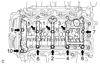
Uniformly tighten the 10 bolts in several steps in the order shown in the illustration.
- Torque:
- 27 N*m { 275 kgf*cm, 20 ft.*lbf }
-
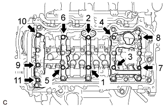
Uniformly tighten the 11 bolts in several steps in the order shown in the illustration.
- Torque:
- 16 N*m { 163 kgf*cm, 12 ft.*lbf }
-
Check the torque of each bolt again.
-
-
TIGHTEN CAMSHAFT TIMING GEAR BOLT
Text in Illustration *a Identification Mark Stamp Note
There are different types of camshaft timing gear bolts. Make sure to check the identification mark to determine the tightening torque.
Identification Mark Item Identification Mark Stamp Type A A Type B D
-
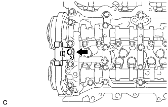
Text in Illustration *a Slack Check that there is some slack in the chain sub-assembly as shown in the illustration.
-
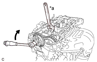
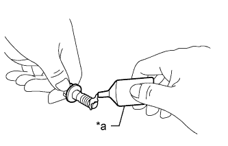
Text in Illustration *a Hold 
Turn Use a wrench to hold the hexagonal portion of the camshaft.
-
Tighten the camshaft timing gear bolt.
- Torque:
- Type A
- 120 N*m { 1224 kgf*cm, 89 ft.*lbf }
- Type B
- 95 N*m { 969 kgf*cm, 70 ft.*lbf }
Note
Be careful not to damage the cylinder head sub-assembly or spark plug tube with the wrench.
-
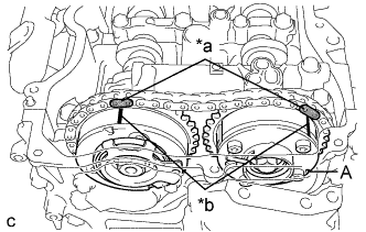
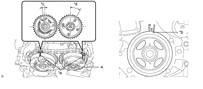
Text in Illustration *a Paint Mark *b Timing Mark Check that the paint marks of the chain sub-assembly are aligned with the timing mark of the camshaft timing gear assembly and the camshaft timing exhaust gear assembly.
Tech Tips
"A" is not a timing mark.
-
-
ADD ENGINE OIL
-
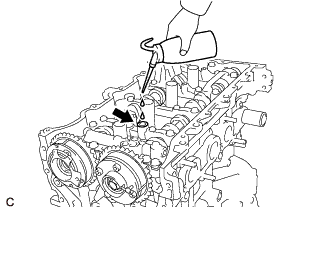
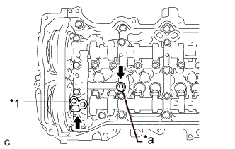
Add 50 cc (3.1 cu. in.) of engine oil into the oil hole shown in the illustration.
Note
-
Engine oil must be added if the valve lash adjuster assemblies were removed.
-
Make sure that the low pressure chamber and oil paths of the valve lash adjuster assemblies are full of engine oil.
-
-
-
INSTALL TIMING CHAIN GUIDE
-
Install the timing chain guide with the bolt.
- Torque:
- 21 N*m { 214 kgf*cm, 15 ft.*lbf }
-
-
INSTALL NO. 1 CHAIN TENSIONER ASSEMBLY
-
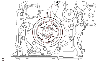
Turn the crankshaft pulley approximately 15° clockwise.
-
Install a new gasket and the No. 1 chain tensioner assembly with the 2 bolts.
- Torque:
- 10 N*m { 102 kgf*cm, 7 ft.*lbf }
Note
Make sure not to drop the gasket inside the timing chain cover sub-assembly.
-
Remove the pin from the stopper plate.
-
-
SET NO. 1 CYLINDER TO TDC/COMPRESSION
-
Turn the crankshaft pulley until its timing notch (groove) and the timing mark "0" of the timing chain cover sub-assembly are aligned.
Text in Illustration *a Timing Mark *b Timing Notch (Groove) *c Approximately 7° *d Approximately 32° -
Check that both timing marks on the camshaft timing gear assembly and camshaft timing exhaust gear assembly are facing upward as shown in the illustration. If not, turn the crankshaft 1 revolution (360°) to align the timing marks as shown in the illustration.
Tech Tips
"A" is not a timing mark.
-
-
INSTALL TIMING CHAIN COVER PLATE
-
Install a new gasket and the timing chain cover plate with the 4 bolts.
- Torque:
- 10 N*m { 102 kgf*cm, 7 ft.*lbf }
-
-
INSTALL CAMSHAFT TIMING OIL CONTROL SOLENOID ASSEMBLY
-
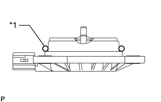
Text in Illustration *1 O-ring Apply engine oil to a new O-ring and install it to the camshaft timing oil control solenoid assembly as shown in the illustration.
Note
Do not damage the O-ring.
-
Text in Illustration *a Adhesive 1324 Apply adhesive to 2 or 3 threads of 2 new bolts.
Adhesive Toyota Genuine Adhesive 1324, Three Bond 1324 or equivalent. -
Install the camshaft timing oil control solenoid assembly to the timing chain cover sub-assembly with the 2 bolts.
- Torque:
- 10 N*m { 102 kgf*cm, 7 ft.*lbf }
Note
-
If the camshaft timing oil control solenoid assembly has been struck or dropped, replace it.
-
Make sure that the O-ring is not cracked or moved out of place when installing the camshaft timing oil control solenoid assembly.
-
Connect the camshaft timing oil control solenoid assembly connector.
-
-
INSTALL CYLINDER HEAD COVER SUB-ASSEMBLY
-
Text in Illustration *1 Camshaft Bearing Cap Oil Hole Gasket *a Gasket Apply a light coat of engine oil to a new camshaft bearing cap oil hole gasket and a new gasket.
-
Install the camshaft bearing cap oil hole gasket to the No. 1 camshaft bearing cap.
-
Install the gasket to the No. 2 camshaft bearing cap.
-
Install a new cylinder head cover gasket to the cylinder head cover sub-assembly.
Note
Remove any oil from the contact surface.
-
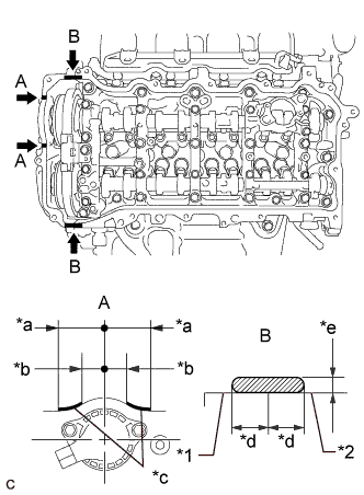
Text in Illustration *1 Timing Chain Cover Sub-assembly *2 Camshaft Housing Sub-assembly *a 45 mm (1.77 in.) *b 24 mm (0.945 in.) *c Seal Packing Diameter: 3.0 mm (0.118 in.) *d Application Width 5.0 mm (0.197 in.) *e Seal Packing Diameter: 3.0 to 6.0 mm (0.118 to 0.236 in.) Seal Packing Apply seal packing as shown in the illustration.
Seal Packing Toyota Genuine Seal Packing Black, Three Bond 1207B or equivalent Note
-
Remove any oil from the contact surface.
-
Install the cylinder head cover sub-assembly within 3 minutes and tighten the bolts within 15 minutes of applying seal packing.
-
-
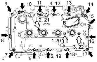
Align the cylinder head cover sub-assembly with the pin (A). Then align the cylinder head cover sub-assembly with the pin (B) and install the cylinder head cover sub-assembly.
Text in Illustration Bolt 
Bolt with Seal Washer -
Install 3 new seal washers and the 17 bolts, and then tighten the bolts in the order shown in the illustration.
- Torque:
- 12 N*m { 122 kgf*cm, 9 ft.*lbf }
Note
Do not start the engine for at least 2 hours after installation.
-
-
CONNECT NO. 2 VENTILATION HOSE
-
Connect the No. 2 ventilation hose to the PCV valve (ventilation valve sub-assembly) and slide the clip to secure it.
-
-
INSTALL IGNITION COIL ASSEMBLY
Tech Tips
Perform "Inspection After Repair" after replacing an ignition coil assembly Click here.
-
Install the 4 ignition coil assemblies to the cylinder head cover sub-assembly with the 4 bolts.
- Torque:
- 10 N*m { 102 kgf*cm, 7 ft.*lbf }
Note
If an ignition coil assembly has been struck or dropped, replace it.
Tech Tips
Install the same parts to their original positions.
-
Connect the 4 ignition coil assembly connectors.
-
-
INSTALL ENGINE MOVING CONTROL ROD BRACKET
-
INSTALL NO. 2 ENGINE MOUNTING STAY RH
-
INSTALL EARTH WIRE
-
INSTALL VACUUM PUMP ASSEMBLY
-
INSTALL FUEL PUMP WITH SEAL SUB-ASSEMBLY (for High Pressure)
-
CONNECT ENGINE WIRE
-
Connect the engine wire to the engine assembly with the 4 nuts and 5 bolts.
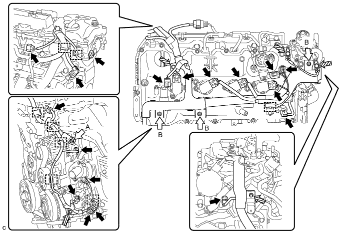
Text in Illustration Connector Nut 
Bolt - - - Torque:
- Nut (A)
- 9.8 N*m { 100 kgf*cm, 87 in.*lbf }
- Nut (B) and Bolt
- 8.0 N*m { 82 kgf*cm, 71 in.*lbf }
-
Connect the 18 connectors and 8 clamps.
-
Engage the clamp to connect the heater inlet water hose.
-
-
INSTALL AIR CLEANER CASE SUB-ASSEMBLY
-
INSTALL AIR CLEANER FILTER ELEMENT SUB-ASSEMBLY
-
INSTALL AIR CLEANER CAP WITH AIR CLEANER HOSE
-
Connect the air cleaner cap with air cleaner hose to the throttle body with motor assembly.
-
Install the air cleaner cap with air cleaner hose with the 2 guides and 2 air cleaner cap clamps.
-
Tighten the hose clamp.
-
Connect the union to connector tube hose to the air cleaner hose sub-assembly.
-
Engage the wire harness clamp.
-
Connect the mass air flow meter sub-assembly connector.
-
Engage the ventilation hose clamp.
-
Connect the ventilation hose to the cylinder head cover sub-assembly and slide the clip to secure it.
-
-
INSTALL INLET AIR CLEANER ASSEMBLY
-
INSTALL NO. 1 ENGINE COVER SUB-ASSEMBLY
-
INSTALL COOL AIR INTAKE DUCT SEAL
-
CONNECT CABLE TO NEGATIVE BATTERY TERMINAL
Note
When disconnecting the cable, some systems need to be initialized after the cable is reconnected Click here.
-
INSPECT FOR ENGINE OIL LEAK
-
INSTALL FRONT FENDER APRON SEAL RH
-
INSTALL ENGINE UNDER COVER RH
-
INSTALL FRONT WHEEL OPENING EXTENSION PAD RH
-
INSTALL FRONT WHEEL RH
- Torque:
- 103 N*m { 1049 kgf*cm, 76 ft.*lbf }
-
OPERATION CHECK