ENGINE UNIT INSTALLATION

Tech Tips
Perform "Inspection After Repair" after replacing the engine assembly Click here.
-
INSTALL BRACKET
-
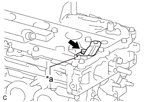
Text in Illustration *a Rib Install the bracket to the cylinder head sub-assembly with the bolt.
- Torque:
- 10 N*m { 102 kgf*cm, 7 ft.*lbf }
Note
Securely install the bracket so that the bracket contacts the rib of the cylinder head cover sub-assembly.
-
-
INSTALL IGNITION COIL ASSEMBLY
Tech Tips
Perform "Inspection After Repair" after replacing an ignition coil assembly Click here.
-
Install the 4 ignition coil assemblies to the cylinder head cover sub-assembly with the 4 bolts.
- Torque:
- 10 N*m { 102 kgf*cm, 7 ft.*lbf }
Note
If an ignition coil assembly has been struck or dropped, replace it.
Tech Tips
Install the same parts to their original positions.
-
Connect the 4 ignition coil assembly connectors.
-
-
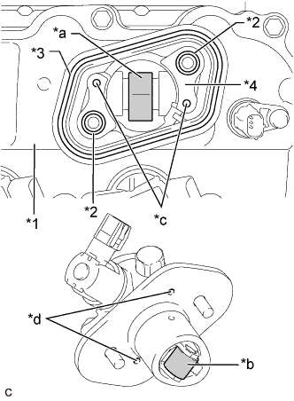
INSTALL WATER INLET HOUSING
Note
If a stud bolt is deformed or its threads are damaged, replace it.
-
Using an E6 "TORX" socket wrench, install the 5 stud bolts to the water inlet housing.
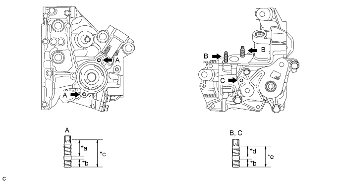
Text in Illustration *a 21 mm (0.827 in.) *b 9.0 mm (0.354 in.) *c 34 mm (1.34 in.) *d 16 mm (0.630 in.) *e 27 mm (1.06 in.) - - - Torque:
- Stud Bolt (A), (B)
- 4.4 N*m { 45 kgf*cm, 39 in.*lbf }
- Torque:
- Stud Bolt (C)
- 4.0 N*m { 41 kgf*cm, 35 in.*lbf }
-
Install a new gasket and the water inlet housing with the 4 bolts and nut.
- Torque:
- 43 N*m { 438 kgf*cm, 32 ft.*lbf }
-
-
INSTALL ENGINE OIL TEMPERATURE SENSOR
-
Install a new gasket to the engine oil temperature sensor.
-
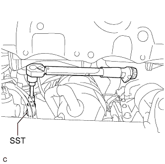
Using SST, install the engine oil temperature sensor to the water inlet housing sub-assembly.
- SST
- 09817-33191
- Torque:
- 19.6 N*m { 200 kgf*cm, 14 ft.*lbf }
Note
If the engine oil temperature sensor has been struck or dropped, replace it.
-
Connect the engine oil temperature sensor connector.
-
-
INSTALL OIL COOLER ASSEMBLY
-
Clean the installation surfaces of the oil cooler assembly.
-
Apply a small amount of engine oil to 3 new gaskets.
-
Install the 3 gaskets to the oil cooler assembly.
-
Temporarily install the oil cooler assembly with the oil cooler union bolt, nut and a new seal washer.
-
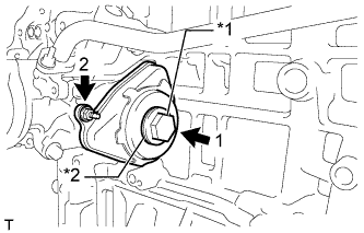
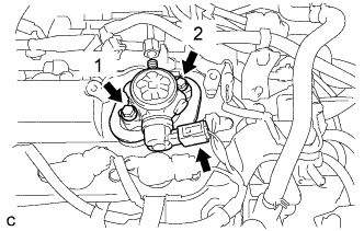
Using several steps, uniformly install and tighten the oil cooler union bolt and nut in the order shown in the illustration.
- Torque:
- Oil Cooler Union Bolt
- 60 N*m { 612 kgf*cm, 44 ft.*lbf }
- Nut
- 10 N*m { 102 kgf*cm, 7 ft.*lbf }
-
-
INSTALL THERMOSTAT
-
Install a new gasket to the thermostat.
-
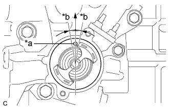
Text in Illustration *a Jiggle Valve *b 10° Install the thermostat to the water inlet housing.
Note
The jiggle valve may be set within 10° on either side of the prescribed position.
-
-
INSTALL WATER INLET
-
Install the water inlet with the 2 nuts.
- Torque:
- 10 N*m { 102 kgf*cm, 7 ft.*lbf }
-
-
INSTALL ENGINE WATER PUMP ASSEMBLY
-
Install a new water pump gasket and the engine water pump assembly with the 7 bolts.
- Torque:
- 21 N*m { 214 kgf*cm, 15 ft.*lbf }
-
-
INSTALL NO. 1 WATER BY-PASS PIPE
-
Install a new gasket and the No. 1 water by-pass pipe with the 2 nuts and bolt.
- Torque:
- 10 N*m { 102 kgf*cm, 7 ft.*lbf }
-
-
INSTALL V-RIBBED BELT TENSIONER ASSEMBLY
-
Install the V-ribbed belt tensioner assembly with the bolt.
- Torque:
- 21 N*m { 214 kgf*cm, 15 ft.*lbf }
-
Install the dust cover to the V-ribbed belt tensioner assembly.
-
-
INSTALL FUEL INJECTOR SEAL
-
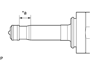
Text in Illustration *a Area to be Cleaned Apply engine conditioner to the area shown in the illustration. Using a piece of cloth, clean carbon deposits from the direct fuel injector assembly and its grooves.
Note
-
Do not clean the tip of the direct fuel injector assembly.
-
Do not use a wire brush to clean the direct fuel injector assembly.
-
If a direct fuel injector assembly is dropped or the tip of a direct fuel injector assembly is struck, replace it with a new one.
-
-
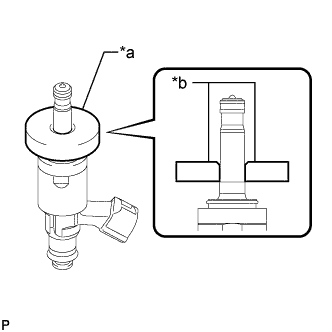
Text in Illustration *a SST (Guide) *b Chamfer Apply engine oil to the direct fuel injector assembly contact surface of SST (guide), then attach SST (guide) to the direct fuel injector assembly with the chamfer facing the tip of the direct fuel injector assembly as shown in the illustration.
- SST
- 09260-39021 ( 09261-03020 )
-
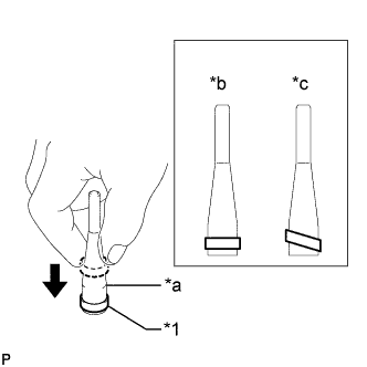
Text in Illustration *1 Fuel Injector Seal *a SST (Holder) *b Correct *c Incorrect Install a new fuel injector seal to SST (holder).
- SST
- 09260-39021 ( 09261-03011 )
Note
Be careful not to install the fuel injector seal to SST (holder) at an angle. Doing so will stretch the fuel injector seal.
-
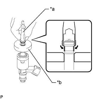
Text in Illustration *a SST (Holder) *b SST (Guide) Install SST (holder) with the fuel injector seal to the tip of the direct fuel injector assembly. Slide the fuel injector seal downward into the direct fuel injector assembly groove with your fingers as shown in the illustration.
- SST
- 09260-39021 ( 09261-03011, 09261-03020 )
Note
Check that the fuel injector seal is seated in the direct fuel injector assembly groove as shown in the illustration.
-
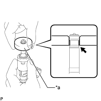
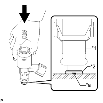
Text in Illustration *a SST (Guide) Slowly slide SST (guide) toward the tip of the direct fuel injector assembly. When the direct fuel injector assembly contact surface of SST (guide) aligns with the fuel injector seal as shown in the illustration, hold the position for 5 seconds or more to fully seat the fuel injector seal into the direct fuel injector assembly groove.
- SST
- 09260-39021 ( 09261-03020 )
Note
Make sure the fuel injector seal is not pinched between SST (guide) and the edge of the direct fuel injector assembly groove. Replace the fuel injector seal if it becomes damaged.
Tech Tips
-
Set SST (guide) so that its bottom surface is flush with the fuel injector seal.
-
If it is difficult to slide SST (guide) upward, slowly wiggle it from side to side while sliding it up the direct fuel injector assembly little by little.
-
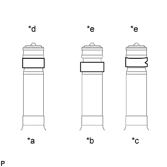
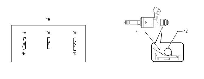
Text in Illustration *a Normal *b Protruding *c Deformed *d Correct *e Incorrect After installing the fuel injector seals, check that they are not scratched, deformed or protruding from the direct fuel injector assembly groove.
Note
If a fuel injector seal is scratched, deformed or protruding from the groove, replace it with a new one.
-
-
INSTALL DIRECT FUEL INJECTOR ASSEMBLY
Note
Perform "Inspection After Repair" after replacing a direct fuel injector assembly Click here.
-
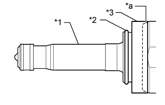
Text in Illustration *1 Direct Fuel Injector Assembly *2 C-ring *3 Injector Vibration Insulator *a Taper Install a new injector vibration insulator and a new C-ring to the direct fuel injector assembly.
Note
-
Install the taper of the injector vibration insulator by aligning it with the taper of the direct fuel injector assembly.
-
Check that the C-ring is securely seated in the groove of the direct fuel injector assembly.
-
-
Install a new O-ring and a new No. 1 fuel injector back-up ring to the direct fuel injector assembly as shown in the illustration.
Text in Illustration *1 No. 1 Fuel Injector Back-up Ring *2 O-ring *a No. 1 Fuel Injector Back-up Ring
Opening
*b Overlapped *c Stretched *d Correct *e Incorrect - - Note
-
Check that there is no foreign matter or damage on the O-ring groove of the direct fuel injector assembly.
-
Make sure that the No. 1 fuel injector back-up ring is installed in the correct orientation.
-
Make sure that the No. 1 fuel injector back-up ring and O-ring are installed in the correct order.
-
Check that the opening of the No. 1 fuel injector back-up ring is not overlapped or stretched as shown in the illustration.
-
After installing the O-ring, check that it is not contaminated with foreign matter and is not damaged.
-
-
Text in Illustration *1 Direct Fuel Injector Assembly *2 No. 3 Fuel Injector Back-up Ring *a Notch With the notch of a new No. 3 fuel injector back-up ring facing downward, install the direct fuel injector assembly to the No. 3 fuel injector back-up ring as shown in the illustration.
Note
-
Make sure that the No. 3 fuel injector back-up ring is installed in the correct orientation.
-
After installing the No. 3 fuel injector back-up ring, make sure there is no damage or foreign matter.
-
-
Install the nozzle holder clamp to each direct fuel injector assembly.
-
Text in Illustration *a Protrusion *b Positioning Hole 
No Gap Align the protrusion of the nozzle holder clamp with the positioning hole of the fuel delivery pipe sub-assembly and insert the direct direct fuel injector assembly.
Note
-
Make sure that there is no foreign matter or damage inside the direct fuel injector assembly installation holes (fuel delivery pipe sub-assembly).
-
Do not allow gasoline to get on the O-rings or inside the installation holes.
-
If it is difficult to insert the direct fuel injector assembly, apply new engine oil to the chamfer of the direct fuel injector assembly installation hole of the fuel delivery pipe sub-assembly. Be careful not to allow the direct fuel injector assembly to fall out of the fuel delivery pipe sub-assembly.
-
Do not tilt the direct fuel injector assembly when inserting it into the fuel delivery pipe sub-assembly.
-
Check that there is no gap between the fuel delivery pipe sub-assembly and the nozzle holder clamp.
-
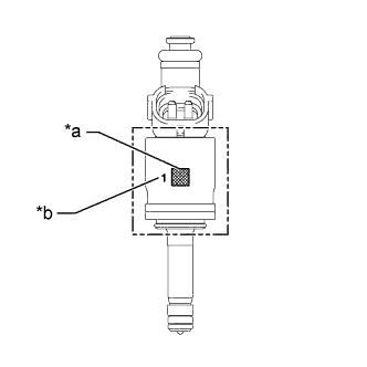
Make sure the 4 direct fuel injector assemblies have the same flow classification number 1, 2 or 3 (the number to the left of the QR code).
Text in Illustration *a QR Code *b Flow Classification Number
-
-
-
INSTALL FUEL DELIVERY PIPE SUB-ASSEMBLY
-
Apply lubricant to the direct fuel injector assembly installation holes of the cylinder head sub-assembly.
-
Text in Illustration *a Protruding enough to install nut Temporarily install the fuel delivery pipe sub- assembly so that the stud bolts protrude enough to install the nuts.
Note
-
If a direct fuel injector assembly is dropped or the tip of a direct fuel injector assembly is struck, replace it with a new one.
-
Check that there is no foreign matter or damage on the direct fuel injector assembly installation holes of the cylinder head sub-assembly.
-
When installing the fuel delivery pipe sub-assembly, push it in evenly without tilting it.
-
-
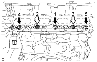
Install the fuel delivery pipe sub-assembly by uniformly tightening the 3 bolts and 2 nuts in the order shown in the illustration.
Text in Illustration Bolt 
Nut - Torque:
- 29 N*m { 296 kgf*cm, 21 ft.*lbf }
-
-
INSTALL NO. 5 ENGINE WIRE
-
Engage the 2 clamps and install the No. 5 engine wire.
-
Connect the fuel pressure sensor connector, knock control sensor connector and 4 fuel injector set connectors.
-
Connect the No. 5 engine wire to the fuel delivery pipe sub-assembly with the 2 bolts.
- Torque:
- 10 N*m { 102 kgf*cm, 7 ft.*lbf }
-
-
INSTALL INTAKE MANIFOLD
-
Install a new manifold gasket to the intake manifold.
-
Temporarily install the intake manifold to the cylinder head sub-assembly with the 6 bolts.
-
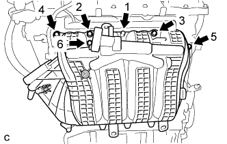
Tighten the 6 bolts in the order shown in the illustration.
- Torque:
- 28 N*m { 286 kgf*cm, 21 ft.*lbf }
-
-
CONNECT NO. 2 VENTILATION HOSE
-
Connect the No. 2 ventilation hose to the PCV valve (ventilation valve sub-assembly) and slide the clip to secure it.
-
-
INSTALL THROTTLE BODY GASKET
-
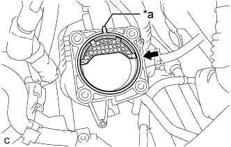
Text in Illustration *a Protrusion Install a new throttle body gasket to the intake manifold with the protrusion of the throttle body gasket oriented as shown in the illustration.
-
-
INSTALL THROTTLE BODY WITH MOTOR ASSEMBLY
-
Connect the No. 2 water by-pass hose and No. 3 water by-pass hose to the throttle body with motor assembly and slide the 2 clips to secure them.
-
Install the throttle body with motor assembly to the intake manifold with the 4 bolts.
- Torque:
- 10 N*m { 102 kgf*cm, 7 ft.*lbf }
Note
If the throttle body with motor assembly has been struck or dropped, replace it.
-
Connect the throttle body with motor assembly connector.
-
-
INSTALL PORT FUEL INJECTOR ASSEMBLY
Tech Tips
Perform "Inspection After Repair" after replacing a port fuel injector assembly Click here.
-
Apply a light coat of spindle oil or gasoline to a new O-ring, and install one to each port fuel injector assembly.
Note
Check that there is no damage or foreign matter on the groove of the port fuel injector assembly when installing each O-ring to the port fuel injector assembly.
-
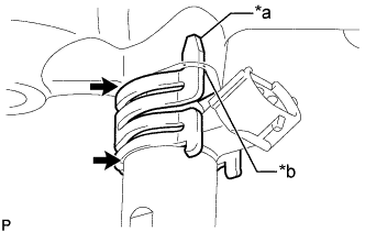
Text in Illustration *a Claw *b Stopper Install the 4 port fuel injector assemblies to the fuel delivery pipe.
Note
-
Make sure that the port fuel injector assembly is located within the stopper as shown in the illustration.
-
Check that there is no damage or foreign matter on the port fuel injector assembly installation holes.
-
When installing the O-rings, make sure they do not become pinched or cut.
-
-
-
INSTALL INJECTOR VIBRATION INSULATOR
-
Install 4 new injector vibration insulators to the cylinder head sub-assembly.
-
-
INSTALL FUEL DELIVERY SPACER
-
Install the 2 fuel delivery spacers to the cylinder head sub-assembly.
-
-
INSTALL FUEL DELIVERY PIPE
-
Place the fuel delivery pipe with the port fuel injector assemblies onto the cylinder head sub-assembly.
Note
Be careful not to drop the port fuel injector assemblies when installing the fuel delivery pipe.
-
Install the fuel delivery pipe with the port fuel injector assemblies with the 2 bolts.
- Torque:
- 21 N*m { 214 kgf*cm, 15 ft.*lbf }
-
-
CONNECT FUEL TUBE SUB-ASSEMBLY (for Port Injection)
Note
Check that there is no damage or foreign matter on the connecting parts of the fuel lines.
-
Connect the fuel tube sub-assembly to the fuel delivery pipe.
-
Text in Illustration *a Retainer *b Fuel Tube Connector *c Nylon Tube *d O-ring *e Fuel Pipe Push Align the fuel tube connector with the fuel pipe, and push them together until the fuel tube connector makes a "click" sound. If it is difficult to push the fuel pipe into the fuel tube connector, apply a small amount of clean engine oil to the tip of the fuel pipe and reinsert it.
-
After connecting the fuel pipes, check that the fuel pipe and fuel tube connector are securely connected by pulling on them.
-
Push in the fuel tube connector cover.
-
-
-
TEMPORARILY INSTALL FUEL PUMP WITH SEAL SUB-ASSEMBLY
-
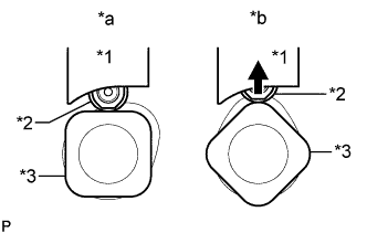
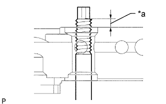
Text in Illustration *1 Fuel Pump Lifter Guide *2 Fuel Pump Lifter Assembly *3 Camshaft *a Correct *b Incorrect Turn the crankshaft pulley until the flat of the camshaft faces the fuel pump with seal sub- assembly installation hole of the cylinder head cover sub-assembly.
Tech Tips
This prevent the camshaft nose from pushing up the fuel pump lifter assembly when installing the fuel pump with seal sub-assembly.
-
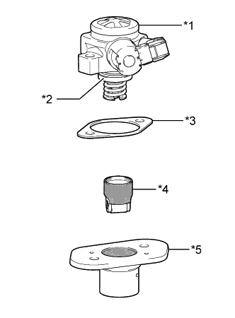
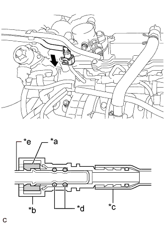
Text in Illustration *1 Fuel Pump with Seal Sub-assembly *2 O-ring *3 Fuel Pump Insulator *4 Fuel Pump Lifter Assembly *5 Fuel Pump Lifter Guide 
Engine Oil Application Area Apply engine oil to a new O-ring and install it to the fuel pump sub-assembly.
-
Apply engine oil to the inside of the fuel pump lifter guide and the outside of the fuel pump lifter assembly.
-
Install the fuel pump lifter assembly to the fuel pump lifter guide.
-
Install the fuel pump insulator to the fuel pump lifter guide.
-
Install the fuel pump with seal sub-assembly to the fuel pump lifter guide.
-
Text in Illustration *1 Cylinder Head Cover Sub-assembly *2 O-ring *3 Fuel Pump Spacer Gasket *4 No. 4 Camshaft Bearing Cap *a Pump Drive Cam (Engine Oil Application Area) *b Pump Lifter (Engine Oil Application Area) *c Knock Pin *d Pin Hole Apply 30 cc (1.8 cu. in.) of engine oil to the pump drive cam.
-
Apply engine oil to the fuel pump lifter assembly.
-
Apply engine oil to 2 new O-rings and install them to the No. 4 camshaft bearing cap.
-
Install a new fuel pump spacer gasket to the cylinder head cover sub-assembly.
-
Set the fuel pump with seal sub-assembly on the cylinder head cover sub-assembly.
-
Temporarily install the fuel pump with seal sub-assembly with the 2 bolts, leaving some allowance for left and right movement.
-
-
TEMPORARILY INSTALL NO. 1 FUEL PIPE SUB-ASSEMBLY
-
Connect the No. 1 fuel pipe sub-assembly to the fuel delivery pipe sub-assembly and tighten the union nut by hand.
-
Connect the No. 1 fuel pipe sub-assembly to the fuel pump with seal sub-assembly and tighten the union nut by hand.
Note
Do not damage the seals of the union nuts of the No. 1 fuel pipe sub-assembly when installing.
-
-
INSTALL FUEL PUMP WITH SEAL SUB-ASSEMBLY
Tech Tips
Perform "Inspection After Repair" after replacing the fuel pump with seal sub-assembly Click here.
-
Tighten the 2 bolts in the order shown in the illustration.
- Torque:
- 30 N*m { 306 kgf*cm, 22 ft.*lbf }
-
Connect the fuel pump with seal sub-assembly connector.
-
-
INSTALL NO. 1 FUEL PIPE SUB-ASSEMBLY
-
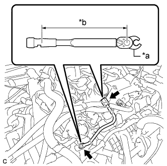
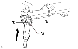
Text in Illustration *a 17 mm Union Nut Wrench *b Torque Wrench Fulcrum Length Using a 17 mm union nut wrench, tighten the union nuts on the fuel pump with seal sub-assembly side of the No. 1 fuel pipe sub-assembly.
- Torque:
- 35 N*m { 357 kgf*cm, 26 ft.*lbf }
Tech Tips
-
Calculate the torque wrench reading when changing the fulcrum length of the torque wrench Click here.
-
When using a 17 mm union nut wrench (fulcrum length of 30 mm (1.18 in.)) + torque wrench (fulcrum length of 180 mm (7.09 in.)): 30 N*m (306 kgf*cm, 22 ft.*lbf)
-
Using a 17 mm union nut wrench, tighten the union nuts on the fuel delivery pipe sub-assembly side of the No. 1 fuel pipe sub-assembly.
- Torque:
- 35 N*m { 357 kgf*cm, 26 ft.*lbf }
Tech Tips
-
Calculate the torque wrench reading when changing the fulcrum length of the torque wrench Click here.
-
When using a 17 mm union nut wrench (fulcrum length of 30 mm (1.18 in.)) + torque wrench (fulcrum length of 180 mm (7.09 in.)): 30 N*m (306 kgf*cm, 22 ft.*lbf)
-
-
INSTALL NO. 1 FUEL PIPE
-
Install the No. 1 fuel pipe and a new gasket to the fuel pump with seal sub-assembly.
- Torque:
- 40 N*m { 408 kgf*cm, 30 ft.*lbf }
-
-
CONNECT FUEL TUBE SUB-ASSEMBLY (for Direct Injection)
Note
Check that there is no damage or foreign matter on the connecting parts of the fuel lines.
-
Connect the fuel tube sub-assembly to the No. 1 fuel pipe.
-
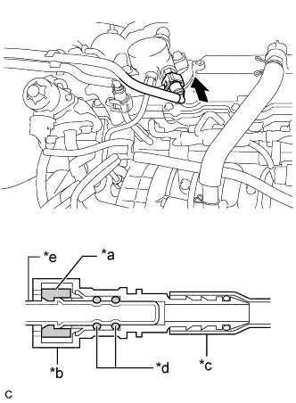
Text in Illustration *a Retainer *b Fuel Tube Connector *c Nylon Tube *d O-ring *e Fuel Pipe Push Align the fuel tube connector with the fuel pipe, and push them together until the fuel tube connector makes a "click" sound. If it is difficult to push the fuel pipe into the fuel tube connector, apply a small amount of clean engine oil to the tip of the fuel pipe and reinsert it.
-
After connecting the fuel pipes, check that the fuel pipe and fuel tube connector are securely connected by pulling on them.
-
Push in the fuel tube connector cover.
-
-
-
INSTALL NO. 1 COMPRESSOR MOUNTING BRACKET
-
Install the No. 1 compressor mounting bracket with the 4 bolts.
- Torque:
- 21 N*m { 214 kgf*cm, 15 ft.*lbf }
-
-
INSTALL EXHAUST MANIFOLD CONVERTER SUB-ASSEMBLY (TWC: Front Catalyst)
-
Install a new exhaust manifold gasket to the cylinder head sub-assembly.
-
Temporarily install the exhaust manifold converter sub-assembly (TWC: Front Catalyst) to the cylinder head sub-assembly with the 5 nuts.
-
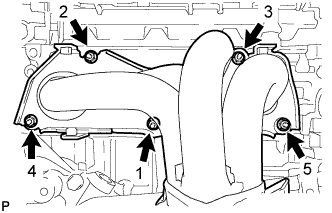
Tighten the 5 nuts in the order shown in the illustration.
- Torque:
- 62 N*m { 632 kgf*cm, 46 ft.*lbf }
-
-
INSTALL NO. 2 MANIFOLD STAY
-
Install the No. 2 manifold stay to the exhaust manifold converter sub-assembly (TWC: Front Catalyst) and stiffening crankcase assembly with the bolt and nut.
- Torque:
- 43 N*m { 438 kgf*cm, 32 ft.*lbf }
-
-
INSTALL MANIFOLD STAY
-
Install the manifold stay to the exhaust manifold converter sub-assembly (TWC: Front Catalyst) and stiffening crankcase assembly with the bolt and nut.
- Torque:
- 43 N*m { 438 kgf*cm, 32 ft.*lbf }
-
-
INSTALL NO. 1 EXHAUST MANIFOLD HEAT INSULATOR
-
Install the No. 1 exhaust manifold heat insulator to the exhaust manifold converter sub-assembly (TWC: Front Catalyst) with the 4 bolts.
- Torque:
- 12 N*m { 122 kgf*cm, 9 ft.*lbf }
-
-
INSTALL EGR VALVE WITH COOLER ASSEMBLY
-
Install a new No. 2 EGR pipe gasket to the EGR valve assembly.
-
Install a new EGR cooler gasket to the EGR pipe connector.
-
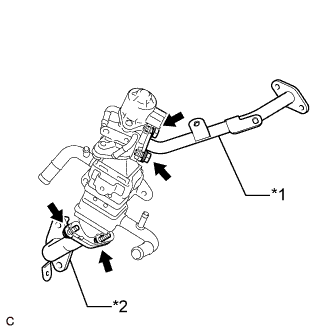
Text in Illustration *1 No. 2 EGR Pipe *2 EGR Pipe Connector Temporarily connect the No. 2 EGR pipe to the EGR valve assembly with the 2 bolts.
-
Temporarily connect the EGR pipe connector to the EGR cooler assembly with the 2 bolts.
-
Install a new EGR cooler gasket to the EGR pipe connector.
-
Install a new EGR inlet gasket to the intake manifold.
-
Temporarily install the EGR valve with cooler assembly, No. 2 EGR pipe and EGR pipe connector to the cylinder head sub-assembly, cylinder block sub-assembly, intake manifold and exhaust manifold converter sub-assembly (TWC: Front Catalyst) with the 4 bolts and 3 nuts.
-
Tighten the 8 bolts and 3 nuts in the order shown in the illustration.
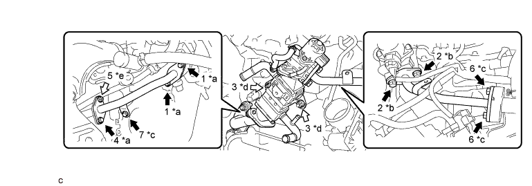
Text in Illustration *a Bolt (A) *b Bolt (B) *c Bolt (C) *d Nut (A) *e Nut (B) - - Bolt Nut - Torque:
- Bolt (A) and Nut (B)
- 36 N*m { 367 kgf*cm, 27 ft.*lbf }
- Bolt (B)
- 25 N*m { 255 kgf*cm, 18 ft.*lbf }
- Bolt (C)
- 10 N*m { 102 kgf*cm, 7 ft.*lbf }
- Nut (A)
- 21 N*m { 214 kgf*cm, 15 ft.*lbf }
-
Engage the 2 wire harness clamps to the No. 2 EGR pipe.
-
Temporarily install the 2 EGR valve brackets with the 4 bolts.
-
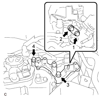
Tighten the 4 bolts in the order shown in the illustration.
- Torque:
- 21 N*m { 214 kgf*cm, 15 ft.*lbf }
-
Install the fuel hose bracket to the EGR valve bracket with the engine cover joint.
- Torque:
- 13 N*m { 133 kgf*cm, 10 ft.*lbf }
-
Connect the No. 4 water by-pass hose to the EGR cooler assembly and slide the clip to secure it.
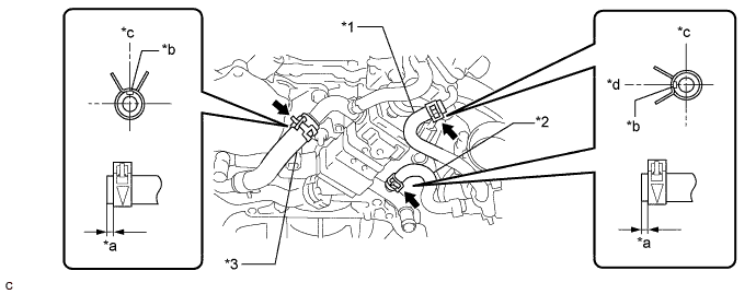
Text in Illustration *1 No. 2 Water By-pass Hose *2 No. 3 Water By-pass Hose *3 No. 4 Water By-pass Hose - - *a 1 to 6 mm (0.0394 to 0.236 in.) *b Paint Mark *c Upper *d Left Tech Tips
Make sure the direction of the clip is as shown in the illustration.
-
Connect the No. 3 water by-pass hose to the EGR cooler assembly and slide the clip to secure it.
Tech Tips
Make sure the direction of the clip is as shown in the illustration.
-
Connect the No. 2 water by-pass hose to the EGR valve assembly and slide the clip to secure it.
Tech Tips
Make sure the direction of the clip is as shown in the illustration.
-
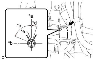
Text in Illustration *a Upper *b Front *c 75° *d 15° *b Paint Mark Connect the water hose sub-assembly to the EGR cooler assembly and slide the clip to secure it.
Tech Tips
Engage the clip within the area shown in the illustration.
-
Engage the water hose to the hose clamp.
-
Connect the EGR valve assembly connector.
-
-
INSTALL FUEL PUMP PROTECTOR
-
Install the fuel pump protector to the cylinder head cover sub-assembly with the 2 bolts.
- Torque:
- 21 N*m { 214 kgf*cm, 15 ft.*lbf }
-
-
INSTALL ENGINE OIL LEVEL DIPSTICK GUIDE
-
Apply a light coat of engine oil to a new O-ring.
-
Install the O-ring to the engine oil level dipstick guide.
-
Install the engine oil level dipstick guide with the bolt.
- Torque:
- 10 N*m { 102 kgf*cm, 7 ft.*lbf }
-
Install the engine oil level dipstick.
-