ENGINE UNIT REMOVAL

-
REMOVE ENGINE OIL LEVEL DIPSTICK GUIDE
-
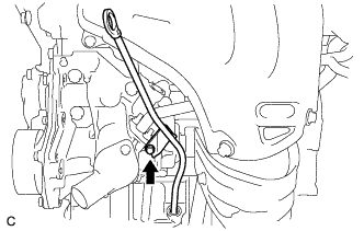
Remove the engine oil level dipstick.
-
Remove the bolt and engine oil level dipstick guide.
-
Remove the O-ring from the engine oil level dipstick guide.
-
-
REMOVE NO. 1 EXHAUST MANIFOLD HEAT INSULATOR
-
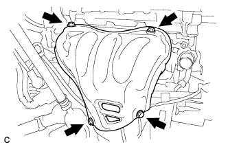
Remove the 4 bolts and No. 1 exhaust manifold heat insulator from the exhaust manifold converter sub-assembly (TWC: Front Catalyst).
-
-
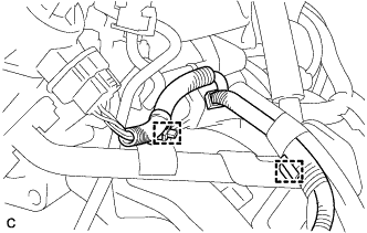
REMOVE EGR PIPE CONNECTOR
-
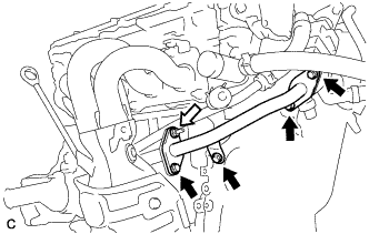
Remove the 4 bolts, nut and EGR pipe connector from the exhaust manifold converter sub-assembly (TWC: Front Catalyst), EGR cooler assembly and cylinder block sub-assembly.
Text in Illustration 
Bolt 
Nut -
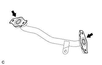
Remove the 2 EGR cooler gaskets from the EGR pipe connector.
-
-
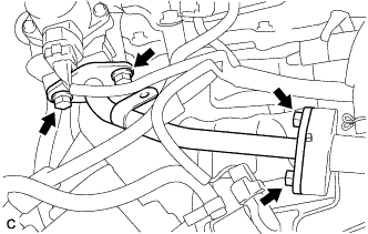
REMOVE MANIFOLD STAY
-
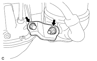
Remove the bolt, nut and manifold stay from the exhaust manifold converter sub-assembly (TWC: Front Catalyst) and stiffening crankcase assembly.
-
-
REMOVE NO. 2 MANIFOLD STAY
-
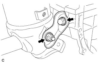
Remove the bolt, nut and No. 2 manifold stay from the exhaust manifold converter sub-assembly (TWC: Front Catalyst) and stiffening crankcase assembly.
-
-
REMOVE EXHAUST MANIFOLD CONVERTER SUB-ASSEMBLY (TWC: Front Catalyst)
-
Remove the 5 nuts and exhaust manifold converter sub-assembly (TWC: Front Catalyst) from the cylinder head sub-assembly.
-
Remove the exhaust manifold gasket from the cylinder head sub-assembly.
-
-
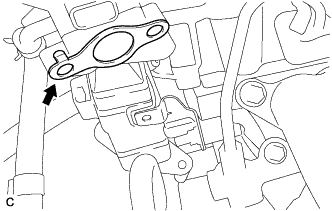
REMOVE NO. 1 COMPRESSOR MOUNTING BRACKET
-
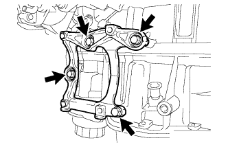
Remove the 4 bolts and No. 1 compressor mounting bracket.
-
-
REMOVE FUEL PUMP PROTECTOR
-
Remove the 2 bolts and fuel pump protector from the cylinder head cover sub-assembly.
-
-
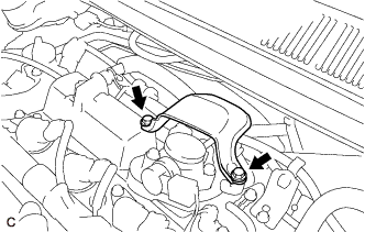
DISCONNECT FUEL TUBE SUB-ASSEMBLY (for Direct Injection)
Note
Remove any foreign matter on the fuel tube connector and fuel pipe before performing this work.
-
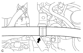
Disconnect the fuel tube sub-assembly from the No. 1 fuel pipe.
-

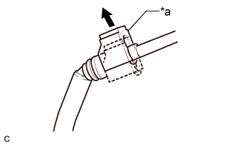
Text in Illustration *a Fuel Tube Connector Cover Pull off Pull off the fuel tube connector cover.
-
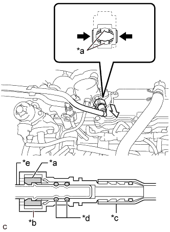
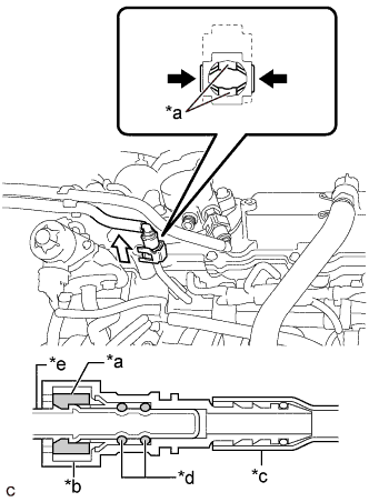
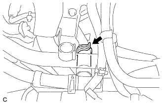
Text in Illustration *a Retainer *b Fuel Tube Connector *c Nylon Tube *d O-ring *e Fuel Pipe Pinch Pull Pinch the retainer of the fuel tube connector, and then pull the fuel tube connector off of the fuel pipe.
Note
Be sure to disconnect the fuel tube connector by hand.
-
If the fuel tube connector and fuel pipe are stuck, push and pull the fuel tube connector to release it. Pull the fuel tube connector off of the fuel pipe carefully.
Note
-
Be sure to disconnect the fuel tube connector by hand.
-
Do not scratch or allow any foreign matter to get on the parts when disconnecting them as the fuel tube connector has O-rings that seal the pipe (fuel pipe).
-
Do not bend, twist, pinch or kink the nylon tube.
-
-
Check that there is no foreign matter on the sealing surfaces of the disconnected fuel lines. Clean them if necessary.
-
Cover the disconnected fuel pipe and fuel tube connector with plastic bags to prevent damage and contamination.
-
-
-
REMOVE NO. 1 FUEL PIPE
-
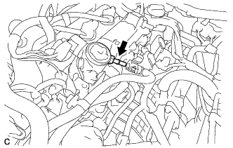
Remove the No. 1 fuel pipe and gasket from the fuel pump with seal sub-assembly.
-
-
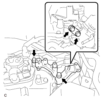
REMOVE NO. 1 FUEL PIPE SUB-ASSEMBLY
-
Using a 17 mm union nut wrench, loosen the 2 union nuts of the No. 1 fuel pipe sub-assembly.
-
Loosen the 2 bolts of the fuel pump with seal sub- assembly.
-
Remove the No. 1 fuel pipe sub-assembly from the fuel delivery pipe sub-assembly and fuel pump with seal sub- assembly.
-
-
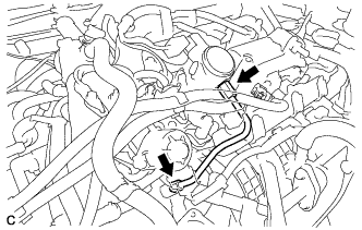
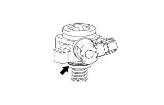
REMOVE FUEL PUMP WITH SEAL SUB-ASSEMBLY
-
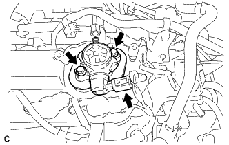
Disconnect the fuel pump with seal sub-assembly connector.
-
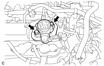
Remove the 2 bolts and fuel pump with seal sub- assembly from the cylinder head cover sub- assembly.
-
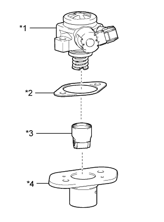
Text in Illustration *1 Fuel Pump with Seal Sub-assembly *2 Fuel Pump Insulator *3 Fuel Pump Lifter Assembly *4 Fuel Pump Lifter Guide Remove the fuel pump lifter guide, fuel pump lifter assembly and fuel pump insulator from the fuel pump with seal sub-assembly.
-
Remove the O-ring from the fuel pump sub- assembly.
-
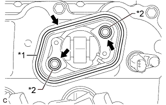
Text in Illustration *1 Fuel Pump Spacer Gasket *2 O-ring Remove the fuel pump spacer gasket from the cylinder head cover sub-assembly.
-
Remove the 2 O-rings from the No. 4 camshaft bearing cap.
-
-
DISCONNECT FUEL TUBE SUB-ASSEMBLY (for Port Injection)
Note
Remove any foreign matter on the fuel tube connector and fuel pipe before performing this work.
-
Disconnect the fuel tube sub-assembly from the fuel delivery pipe.
-
Text in Illustration *a Fuel Tube Connector Cover Pull off Pull off the fuel tube connector cover.
-
Text in Illustration *a Retainer *b Fuel Tube Connector *c Nylon Tube *d O-ring *e Fuel Pipe Pinch Pull Pinch the retainer of the fuel tube connector, and then pull the fuel tube connector off of the fuel pipe.
Note
Be sure to disconnect the fuel tube connector by hand.
-
If the fuel tube connector and fuel pipe are stuck, push and pull the fuel tube connector to release it. Pull the fuel tube connector off of the fuel pipe carefully.
Note
-
Be sure to disconnect the fuel tube connector by hand.
-
Do not scratch or allow any foreign matter to get on the parts when disconnecting them as the fuel tube connector has O-rings that seal the pipe (fuel pipe).
-
Do not bend, twist, pinch or kink the nylon tube.
-
-
Check that there is no foreign matter on the sealing surfaces of the disconnected fuel lines. Clean them if necessary.
-
Cover the disconnected fuel pipe and fuel tube connector with plastic bags to prevent damage and contamination.
-
-
-
REMOVE FUEL DELIVERY PIPE
-
Remove the 2 bolts and fuel delivery pipe with the port fuel injector assemblies.
Note
Be careful not to drop the port fuel injector assemblies when removing the fuel delivery pipe.
-
-
REMOVE FUEL DELIVERY SPACER
-
Remove the 2 fuel delivery spacers from the cylinder head sub-assembly.
-
-
REMOVE INJECTOR VIBRATION INSULATOR
-
Remove the 4 injector vibration insulators from the cylinder head sub-assembly.
-
-
REMOVE PORT FUEL INJECTOR ASSEMBLY
-
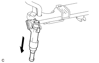
Pull the 4 port fuel injector assemblies out of the fuel delivery pipe.
-
Remove the O-ring from each port fuel injector assembly.
-
Attach a tag or label with the corresponding cylinder number to each port fuel injector assembly so that they can be installed to their original locations.
Note
Cover the port fuel injector assemblies with plastic bags to prevent damage and contamination.
-
-
REMOVE THROTTLE BODY WITH MOTOR ASSEMBLY
-
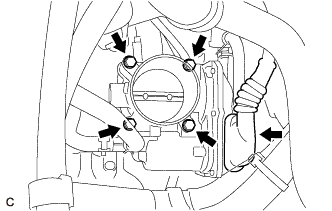
Disconnect the throttle body with motor assembly connector.
-
Remove the 4 bolts and throttle body with motor assembly from the intake manifold.
Note
If the throttle body with motor assembly has been struck or dropped, replace it.
-
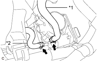
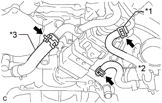
Text in Illustration *1 No. 2 Water By-pass Hose *2 No. 3 Water By-pass Hose Slide the 2 clips and disconnect the No. 2 water by-pass hose and No. 3 water by-pass hose from the throttle body with motor assembly.
-
-
REMOVE THROTTLE BODY GASKET
-
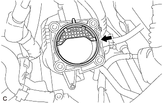
Remove the throttle body gasket from the intake manifold.
-
-
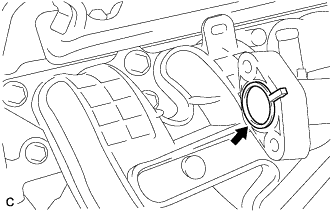
DISCONNECT NO. 2 VENTILATION HOSE
-
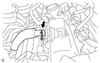
Slide the clip and disconnect the No. 2 ventilation hose from the PCV valve (ventilation valve sub-assembly).
-
-
REMOVE NO. 2 EGR PIPE
-
Disengage the 2 wire harness clamps from the No. 2 EGR pipe.
-
Remove the 4 bolts and No. 2 EGR pipe from the EGR valve assembly and intake manifold.
-
Remove the No. 2 EGR pipe gasket from the EGR valve assembly.
-
Remove the EGR inlet gasket from the intake manifold.
-
-
REMOVE INTAKE MANIFOLD
-
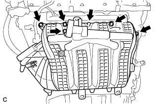
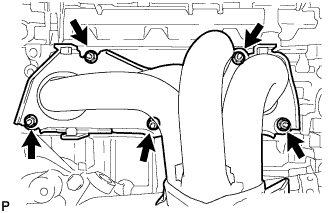
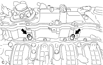
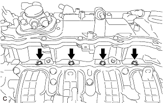
Remove the 6 bolts and intake manifold from the cylinder head sub-assembly.
-
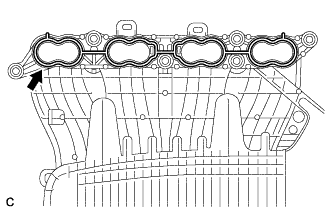
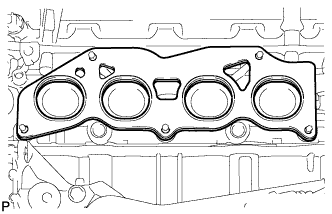
Remove the manifold gasket from the intake manifold.
-
-
REMOVE NO. 5 ENGINE WIRE
-
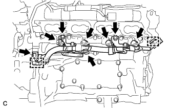
Remove the 2 bolts and disconnect the No. 5 engine wire from the fuel delivery pipe sub-assembly.
-
Disconnect the fuel pressure sensor connector, knock control sensor connector and 4 fuel injector set connectors.
-
Disengage the 2 clamps and remove the No. 5 engine wire.
-
-
REMOVE FUEL DELIVERY PIPE SUB-ASSEMBLY
-
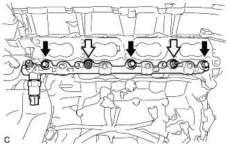
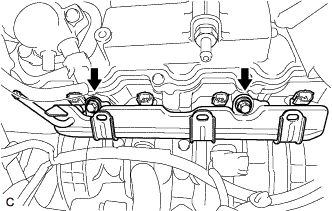
Remove the 3 bolts, 2 nuts and fuel delivery pipe sub-assembly with the direct fuel injector assemblies.
Text in Illustration Bolt Nut Note
-
Make sure not to touch or strike the tips of the direct fuel injector assemblies.
-
Pull and remove the fuel delivery pipe sub-assembly in a straight line without tilting it.
-
-
-
REMOVE DIRECT FUEL INJECTOR ASSEMBLY
-
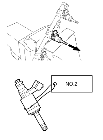
Secure the fuel delivery pipe sub-assembly in a vise between aluminum plates and pull out the 4 direct fuel injector assemblies.
Note
-
Pull and remove each direct fuel injector assembly in a straight line to avoid damaging the seal surface of the fuel delivery pipe sub-assembly O-ring.
-
Attach a tag or label with the corresponding cylinder number to each direct fuel injector assembly so that they can be installed to their original locations.
-
-
Remove the nozzle holder clamp from each direct fuel injector assembly.
-
Using needle nose pliers, remove the No. 3 fuel injector back-up ring from each direct fuel injector assembly.
-
Remove the O-ring and No. 1 fuel injector back-up ring from each direct fuel injector assembly.
-
Remove the C-ring and injector vibration insulator from each direct fuel injector assembly.
-
-
REMOVE FUEL INJECTOR SEAL
-
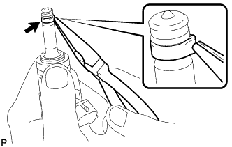
Using the tip of needle nose pliers, pinch and pull the fuel injector seal at several points to stretch it.
Note
-
Excessively pinching the fuel injector seal may damage the groove of the direct fuel injector assembly.
-
If a direct fuel injector assembly is dropped or the tip of a direct fuel injector assembly is struck, replace it with a new one.
-
-
Remove the fuel injector seal from each direct fuel injector assembly.
-
-
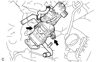
REMOVE EGR VALVE WITH COOLER ASSEMBLY
-
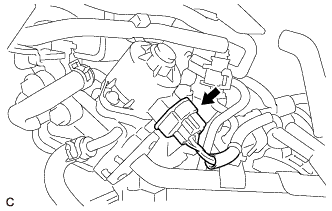
Disconnect the EGR valve assembly connector.
-
Remove the engine cover joint and separate the fuel hose bracket from the EGR valve bracket.
-
Remove the 4 bolts and 2 EGR valve brackets.
-
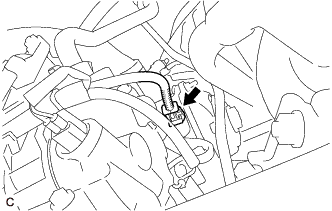
Disengage the water hose from the hose clamp.
-
Slide the clip and disconnect the water hose sub-assembly from the EGR cooler assembly.
-
Text in Illustration *1 No. 2 Water By-pass Hose *2 No. 3 Water By-pass Hose *3 No. 4 Water By-pass Hose Slide the clip and disconnect the No. 2 water by-pass hose from the EGR valve assembly.
-
Slide the clip and disconnect the No. 3 water by-pass hose from the EGR cooler assembly.
-
Slide the clip and disconnect the No. 4 water by-pass hose from the EGR cooler assembly.
-
Remove the 2 nuts and EGR valve with cooler assembly from cylinder head sub-assembly.
-
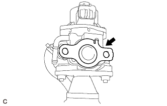
Remove the No. 2 EGR pipe gasket from the EGR valve assembly.
-
-
REMOVE V-RIBBED BELT TENSIONER ASSEMBLY
-
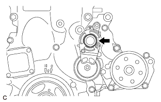
Remove the dust cover from the V-ribbed belt tensioner assembly.
-
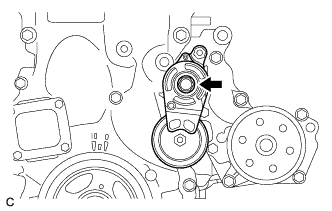
Remove the bolt and V-ribbed belt tensioner assembly from the water inlet housing.
-
-
REMOVE NO. 1 WATER BY-PASS PIPE
-
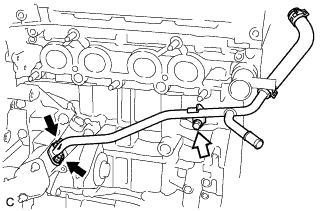
Remove the bolt, 2 nuts and No. 1 water by-pass pipe and gasket.
Text in Illustration Nut Bolt
-
-
REMOVE ENGINE WATER PUMP ASSEMBLY
-
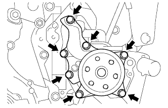
Remove the 7 bolts, engine water pump assembly and water pump gasket.
-
-
REMOVE WATER INLET
-
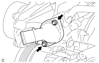
Remove the 2 nuts and water inlet.
-
-
REMOVE THERMOSTAT
-
Remove the thermostat from the water inlet housing.
-
Remove the gasket from the thermostat.
-
-
REMOVE OIL COOLER ASSEMBLY
-
Text in Illustration *1 Oil Cooler Union Bolt *2 Seal Washer Remove the oil cooler union bolt and seal washer.
-
Remove the nut and oil cooler assembly from the water inlet housing.
-
Remove the 3 gaskets from the oil cooler assembly.
-
-
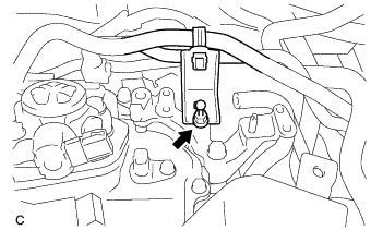
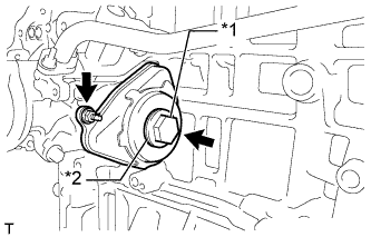
REMOVE ENGINE OIL TEMPERATURE SENSOR
-
Disconnect the engine oil temperature sensor connector.
-
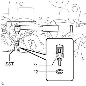
Text in Illustration *1 Engine Oil Temperature Sensor *2 Gasket Using SST, remove the engine oil temperature sensor from the water inlet housing sub-assembly.
- SST
- 09817-33191
Note
If the engine oil temperature sensor has been struck or dropped, replace it.
-
Remove the gasket from the engine oil temperature sensor.
-
-
REMOVE WATER INLET HOUSING
-
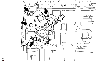
Remove the 4 bolts, nut, water inlet housing and gasket.
Bolt Nut Note
If a stud bolt is deformed or its threads are damaged, replace it.
-
-
REMOVE IGNITION COIL ASSEMBLY
-
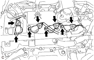
Disconnect the 4 ignition coil assembly connectors.
-
Remove the 4 bolts and 4 ignition coil assemblies from the cylinder head cover sub-assembly.
Note
If an ignition coil assembly has been struck or dropped, replace it.
Tech Tips
Arrange the removed parts in the correct order.
-
-
REMOVE BRACKET
-
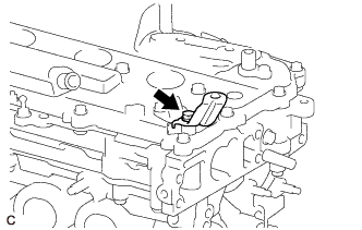
Remove the bolt and bracket from the cylinder head cover sub-assembly.
-