CAMSHAFT REMOVAL
-
PRECAUTION
Note
After turning the engine switch off, waiting time may be required before disconnecting the cable from the negative (-) battery terminal. Therefore, make sure to read the disconnecting the cable from the negative (-) battery terminal notices before proceeding with work Click here.
-
DISCONNECT CABLE FROM NEGATIVE BATTERY TERMINAL
Note
When disconnecting the cable, some systems need to be initialized after the cable is reconnected Click here.
-
REMOVE FRONT WHEEL RH
-
REMOVE FRONT WHEEL OPENING EXTENSION PAD RH
-
REMOVE ENGINE UNDER COVER RH
-
REMOVE FRONT FENDER APRON SEAL RH
-
REMOVE COOL AIR INTAKE DUCT SEAL (for TMC, TMMR Made)
-
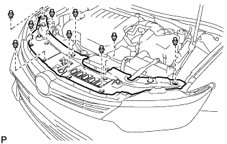
Remove the 9 clips and cool air intake duct seal.
-
-
REMOVE COOL AIR INTAKE DUCT SEAL (for TMMK Made)
-
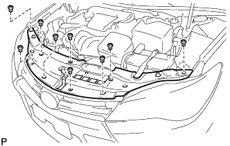
Remove the 9 clips and cool air intake duct seal.
-
-
REMOVE NO. 1 ENGINE COVER SUB-ASSEMBLY
-
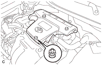
Lift the rear of the engine cover to detach the cover from the 2 pins, and then lift the front of the engine cover to detach the cover from the pin and remove the engine cover.
Note
Attempting to disengage both front and rear clips at the same time may cause the No. 1 engine cover sub-assembly to break.
-
-
REMOVE INLET AIR CLEANER ASSEMBLY
-
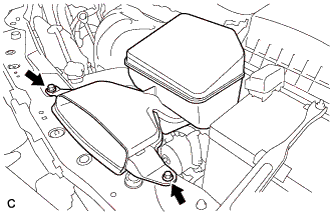
Remove the 2 bolts and inlet air cleaner assembly.
-
-
REMOVE AIR CLEANER CAP SUB-ASSEMBLY
-
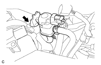
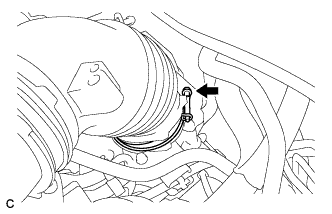
Disconnect the vacuum switching valve assembly from the air cleaner hose.
-
Disconnect the mass air flow meter connector and 2 wire harness clamps from the air cleaner cap sub-assembly.
-
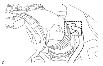
Separate the fuel vapor feed hose from the air cleaner hose.
-
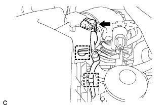
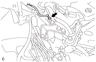
Disconnect the ventilation hose from the cylinder head cover.
-
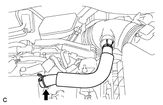
Loosen the hose clamp and disconnect the air cleaner hose from the throttle with motor body assembly.
-
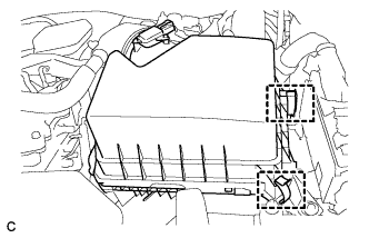
Release the 2 clamps and remove the air cleaner cap sub-assembly.
-
-
REMOVE AIR CLEANER FILTER ELEMENT
-
REMOVE AIR CLEANER CASE SUB-ASSEMBLY
-
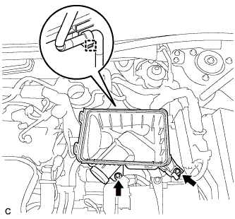
Disconnect the wire harness clamp.
-
Remove the 2 bolts and air cleaner case sub-assembly.
-
-
REMOVE NO. 2 ENGINE MOUNTING STAY RH
-
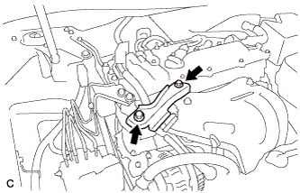
Remove the 2 bolts and No. 2 engine mounting stay RH.
-
-
SEPARATE EARTH WIRE
-
Remove the bolt and separate the earth wire from the engine moving control rod bracket.
-
-
REMOVE ENGINE MOVING CONTROL ROD BRACKET
-
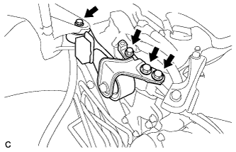
Remove the 4 bolts and engine moving control rod bracket.
-
-
SEPARATE NO. 2 ENGINE ROOM RELAY BLOCK (w/ No. 2 Engine Room Relay Block)
-
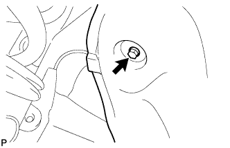
Remove the screw and separate the front fender liner RH.
-
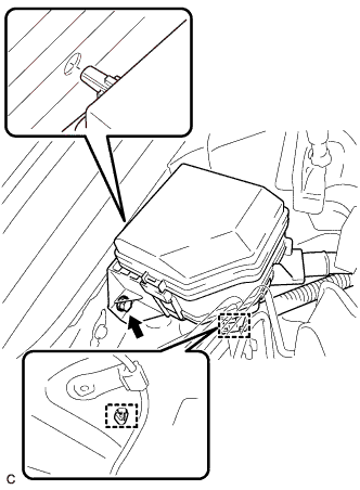
Remove the bolt, disengage the 2 clamps and separate the No. 2 engine room relay block.
-
-
DISCONNECT ENGINE WIRE
-
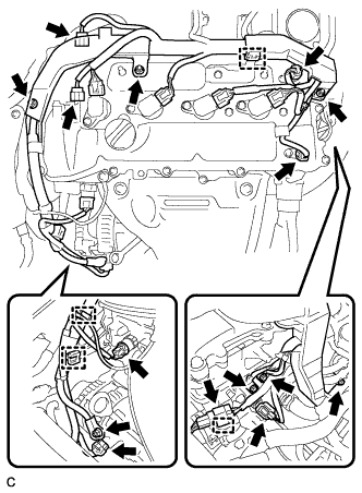
Disconnect the connectors and clamps.
-
Remove the bolts and nuts and disconnect the engine wire from the engine assembly.
-
-
REMOVE IGNITION COIL ASSEMBLY
-
Disconnect the 4 ignition coil assembly connectors.
-
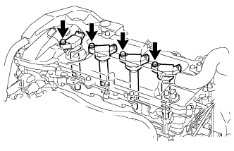
Remove the 4 bolts and 4 ignition coil assemblies.
-
-
REMOVE CYLINDER HEAD COVER SUB-ASSEMBLY
-
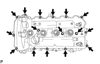
Remove the 16 bolts, 3 seal washers, cylinder head cover and gasket.
-
Remove the 3 gaskets from the camshaft bearing caps.
-
-
SET NO. 1 CYLINDER TO TDC/COMPRESSION
-
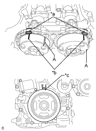
Text in Illustration *a Paint Mark *b Timing Mark *c Timing Notch Turn the crankshaft pulley until its timing notch (groove) and the timing mark "0" of the timing chain cover sub-assembly are aligned.
-
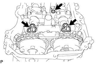
Check that both timing marks on the camshaft timing gear assembly and camshaft timing exhaust gear assembly are facing upward as shown in the illustration. If not, turn the crankshaft 1 revolution (360°) to align the timing marks as shown in the illustration.
Tech Tips
"A" is not a timing mark.
-
Place paint marks on the chain sub-assembly in alignment with the timing marks on the camshaft timing gear assembly and camshaft timing exhaust gear assembly.
-
-
REMOVE TIMING CHAIN COVER PLATE
-
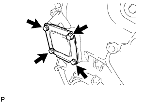
Remove the 4 bolts, timing chain cover plate and gasket.
-
-
REMOVE NO. 1 CHAIN TENSIONER ASSEMBLY
-
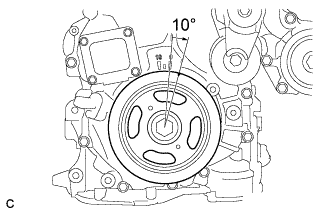
Turn the crankshaft pulley approximately 10° clockwise.
-
Turn the crankshaft pulley approximately 10° counterclockwise.
-
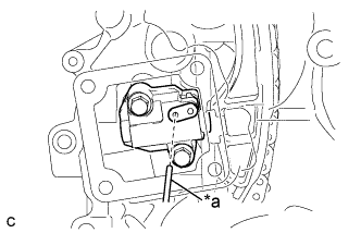
Text in Illustration *a Pin Align the holes of the stopper plate and tensioner, and insert a pin into the stopper plate hole to lock the tensioner.
-
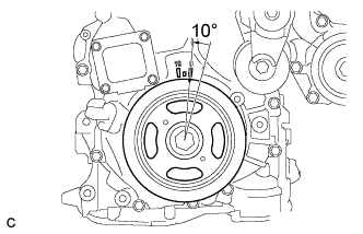
Turn the crankshaft pulley approximately 10° clockwise.
-
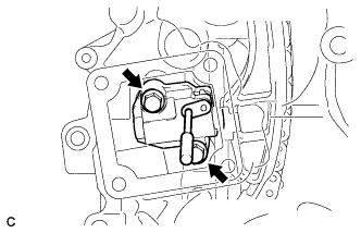
Remove the 2 bolts, No. 1 chain tensioner assembly and gasket.
Note
Make sure not to drop the gasket inside the timing chain cover sub-assembly.
-
Turn the crankshaft pulley approximately 10° counterclockwise.
-
-
REMOVE TIMING CHAIN GUIDE
-
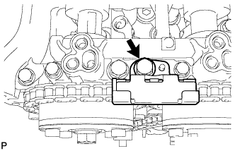
Remove the bolt and timing chain guide.
-
-
REMOVE TIMING CHAIN COVER TIGHT PLUG
-
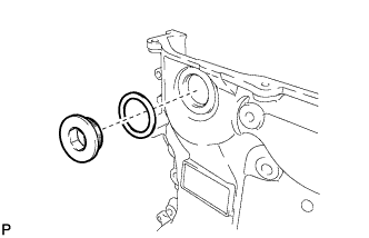
Using a 14 mm hexagon wrench, remove the plug and gasket.
-
-
REMOVE CAMSHAFT TIMING GEAR ASSEMBLY
-
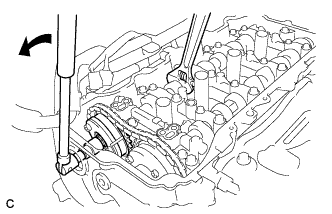
Hold the hexagonal portion of the camshaft with a wrench and remove the bolt from the camshaft.
Note
Be careful not to damage the cylinder head sub-assembly or spark plug tube with the wrench.
-
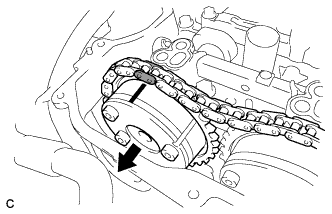
Separate the camshaft timing gear assembly from the camshaft.
-
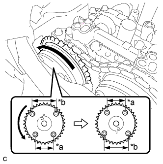
Text in Illustration *a Narrow *b Wide Remove the chain sub-assembly from the camshaft timing gear assembly, and turn the camshaft timing gear assembly approximately 180°.
-
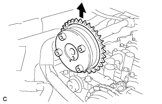
Remove the camshaft timing gear assembly.
Note
Do not disassemble the camshaft timing gear assembly.
-
-
REMOVE CAMSHAFT BEARING CAP
-
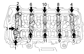
Using several steps, remove the 11 bearing cap bolts in the sequence shown in the illustration.
-
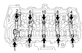
Using several steps, remove the 10 bearing cap bolts in the sequence shown in the illustration.
-
Remove the No. 1 camshaft bearing cap, No. 2 camshaft bearing cap and 3 No. 3 camshaft bearing caps.
Tech Tips
Arrange the removed parts in the correct order.
-
-
REMOVE CAMSHAFT
-
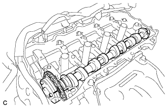
Remove the camshaft from the camshaft housing sub-assembly.
-
-
REMOVE NO. 2 CAMSHAFT
-
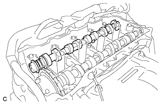
Hold up the chain sub-assembly and remove the No. 2 camshaft from the camshaft housing sub-assembly.
-
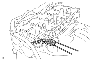
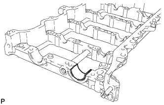
Suspend the chain sub-assembly with a string or equivalent as shown in the illustration.
Note
Be careful not to drop the chain sub-assembly inside the timing chain cover sub-assembly.
-
-
REMOVE CAMSHAFT TIMING EXHAUST GEAR ASSEMBLY
-
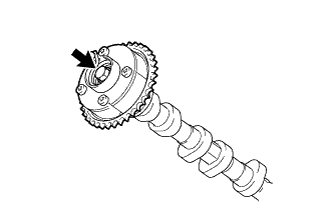
Remove the bolt and camshaft timing exhaust gear assembly.
Note
Do not disassemble the camshaft timing exhaust gear assembly.
-
-
REMOVE OIL CONTROL VALVE FILTER
-
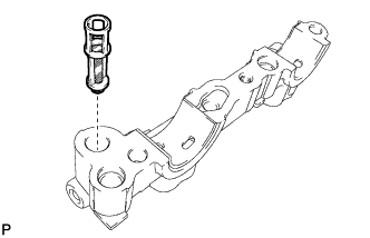
Remove the oil control valve filter from the No. 1 camshaft bearing cap.
-
-
REMOVE NO. 1 CAMSHAFT BEARING
-
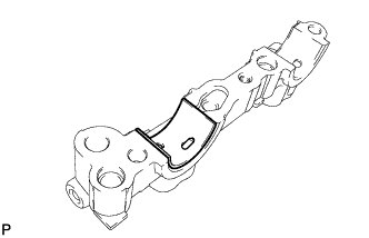
Remove the No. 1 camshaft bearing.
-
-
REMOVE NO. 2 CAMSHAFT BEARING
-
Remove the No. 2 camshaft bearing.
-