AIR FUEL RATIO SENSOR INSTALLATION

-
INSTALL AIR FUEL RATIO SENSOR
Tech Tips
Perform "Inspection After Repair" after replacing the air fuel ratio sensor Click here.
-
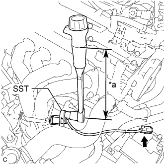
Text in Illustration *a Torque Wrench Fulcrum Length Using SST, install the air fuel ratio sensor to the exhaust manifold.
- SST
- 09224-00011
- Torque:
- Specified tightening torque
- 44 N*m { 449 kgf*cm, 32 ft.*lbf }
Note
If the air fuel ratio sensor has been struck or dropped, replace it.
Tech Tips
-
Calculate the torque wrench reading when changing the fulcrum length of the torque wrench Click here.
-
When using SST (fulcrum length of 30 mm (1.18 in.)) + torque wrench (fulcrum length of 260 mm (10.2 in.)): 39 N*m (398 kgf*cm, 29 ft.*lbf)
-
Connect the air fuel ratio sensor connector.
-
Engage the 3 wire harness clamps.
-
-
INSTALL NO. 1 EXHAUST MANIFOLD HEAT INSULATOR
-
Install the No. 1 exhaust manifold heat insulator to the exhaust manifold converter sub-assembly (TWC: Front Catalyst) with the 4 bolts.
- Torque:
- 12 N*m { 122 kgf*cm, 9 ft.*lbf }
-
-
INSPECT FOR EXHAUST GAS LEAK
If gas is leaking, tighten the areas necessary to stop the leak. Replace damaged parts as necessary.
-
Perform Inspection After Repair after repairing an exhaust gas leak Click here.
-
-
PERFORM INITIALIZATION