SFI SYSTEM, Diagnostic DTC:P019011
| DTC Code | DTC Name |
|---|---|
| P019011 | Fuel Rail Pressure Sensor "A" Circuit Short to Ground |
DESCRIPTION
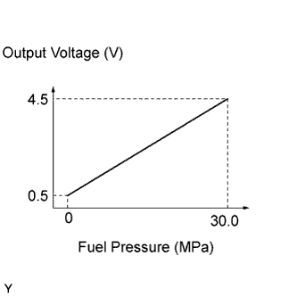
The fuel pressure sensor is installed on the delivery pipe for high pressure side. The fuel pressure sensor changes the fuel pressure for high pressure side into an electrical signal and sends the signal to the ECM. Then the ECM controls the pump discharge using this feedback to maintain the fuel's target pressure between 2 and 25 MPa (20 and 255 kgf/cm2).
| DTC No. | DTC Detection Condition | Trouble Area |
|---|---|---|
| P019011 | The fuel pressure sensor output voltage is less than 0.293 V for 3 seconds or more (1 trip detection logic). |
|
Tech Tips
When this DTC is output, check the fuel pressure (for high pressure side) in the Data List. Enter the following menus: Powertrain / Engine / Data List / All Data / Fuel Pressure (High).
| DTC No. | Fuel Pressure (High) | Malfunction |
|---|---|---|
| P019011 | Approximately 0 kPag |
|
If the Data List values is normal it may be due to a temporary recovery from the malfunction condition. Check for intermittent problems.
MONITOR DESCRIPTION
This DTC is stored if the fuel pressure sensor output voltage is out of the standard range due to an open or short in the sensor circuit.
-
Example:
-
If the fuel pressure sensor output voltage is less than 0.293 V for 3 seconds or more, the ECM store this DTC.
MONITOR STRATEGY
| Required Sensors/Components | Fuel pressure sensor |
| Frequency of Operation | Continuous |
CONFIRMATION DRIVING PATTERN
-
Connect the GTS to the DLC3.
-
Turn the engine switch on (IG) and turn the GTS on.
-
Clear the DTCs (even if no DTCs are stored, perform the clear DTC procedure).
-
Turn the engine switch off and wait for at least 30 seconds.
-
Turn the engine switch on (IG) and turn the GTS on.
-
Start the engine.
-
Idle the engine for 10 seconds.
-
Enter the following menus: Powertrain / Engine / Trouble Codes.
-
Read the pending DTCs.
Tech Tips
-
If a pending DTC is output, the system is malfunctioning.
-
If a pending DTC is not output, perform the following procedure.
-
-
Enter the following menus: Powertrain / Engine / Utility / All Readiness.
-
Input the DTC: P019011.
-
Check the DTC judgment result.
| GTS Display | Description |
|---|---|
| NORMAL |
|
| ABNORMAL |
|
| INCOMPLETE |
|
| N/A |
|
Tech Tips
-
If the judgment result shows NORMAL, the system is normal.
-
If the judgment result shows ABNORMAL, the system has a malfunction.
-
If the judgment result shows INCOMPLETE or N/A, perform the Confirmation Driving Pattern and check the DTC judgment result again.
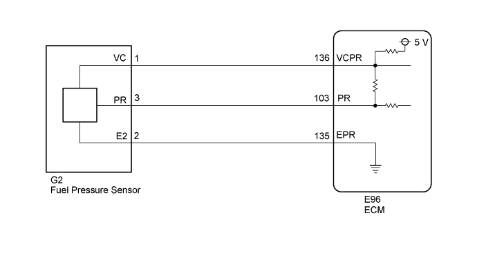
WIRING DIAGRAM
INSPECTION PROCEDURE
Tech Tips
Read freeze frame data using the GTS. The ECM records vehicle and driving condition information as freeze frame data the moment a DTC is stored. When troubleshooting, freeze frame data can help determine if the vehicle was moving or stationary, if the engine was warmed up or not, if the air fuel ratio was lean or rich, and other data from the time the malfunction occurred.
PROCEDURE
-
CHECK HARNESS AND CONNECTOR (FUEL PRESSURE SENSOR - ECM)
-
Disconnect the ECM connector.
-
Disconnect the fuel pressure sensor connector.
-
Measure the resistance according to the value(s) in the table below.
Standard Resistance Tester Connection Condition Specified Condition G2-1 (VC) - E96-136 (VCPR) Always Below 1 Ω G2-3 (PR) or E96-103 (PR) - Body ground and other terminals Always 10 kΩ or higher
NG 
REPAIR OR REPLACE HARNESS OR CONNECTOR
OK 
-
-
CHECK TERMINAL VOLTAGE (POWER SOURCE OF FUEL PRESSURE SENSOR)
-
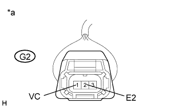
Text in Illustration *a Front view of wire harness connector
(to Fuel Pressure Sensor)
Disconnect the fuel pressure sensor connector.
-
Turn the engine switch on (IG).
-
Measure the voltage according to the value(s) in the table below.
Standard Voltage Tester Connection Condition Specified Condition G2-1 (VC) - G2-2 (E2) Engine switch on (IG) 4.75 to 5.25 V
NG
REPLACE ECM Click here
OK 
REPLACE FUEL DELIVERY PIPE (FUEL PRESSURE SENSOR) Click here
-