REAR WHEEL ALIGNMENT (for TMMK Made) ADJUSTMENT
-
INSPECT TIRES
-
Check the tires for wear and proper inflation pressure.
Cold Tire Inflation Pressure Tire Size Front
kPa (kgf/cm2, psi)
Rear
kPa (kgf/cm2, psi)
P215/55R17 93V 210 (2.1, 30)
-
Perform initialization Click here.
-
-
Tire pressure adjustment method when warm:
Note
for ECE-R64 Type:
If the tire pressure is decreased approximately 20 kPa (0.2 kgf/cm2, 2.9 psi) or more in order to adjust the tire pressure, even if the adjusted tire pressure is 80% or more than the tire pressure set during system initialization, the tire pressure warning light may illuminate if the tire pressure drops below 80% of the tire pressure set when the tires are warmed. In this case, perform initialization again.
-
Turn the engine switch off.
-
Connect the GTS to the DLC3.
-
Turn the engine switch on (IG).
-
Turn the GTS on.
-
Enter the following menus: Chassis / Tire Pressure Monitor / Data List.
-
Adjust the tire pressure so that the displayed value is equal to the set pressure.
-
Perform initialization and check that initialization completes Click here.
-
Check and record the value of the Data List item "Temperature in Tire". (Ts)
-
Check and record the ambient temperature during tire pressure adjustment. (Tm)
-
Readjust the tire pressure according to the difference between the tire internal temperature (Ts) and the ambient temperature (Tm). (P)
Tech Tips
Tire internal temperature: Ts, Ambient temperature: Tm, Tire pressure readjustment value: P
P = (Specified Pressure) + (Ts - Tm)
-
Check the pressure adjustment value with the Data List item "Tire Inflation Pressure".
-
-
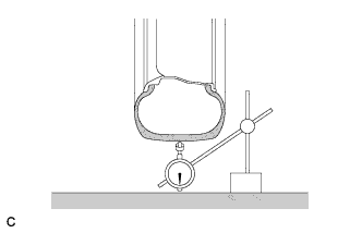
Using a dial indicator, check the runout of the tires.
Maximum Tire Runout 1.4 mm (0.0551 in.)
-
-
MEASURE VEHICLE HEIGHT
Note
-
Before inspecting the wheel alignment, adjust the vehicle height to the specified value.
-
Be sure to perform measurement on a level surface.
-
If it is necessary to go under the vehicle for measurement, confirm that the parking brake is applied and the vehicle is secured with chocks.
-
Inspect while the vehicle is unloaded.
-
The standard value shown here is a value that is used for adjusting the wheel alignment and does not indicate the height of an actual vehicle.
-
Bounce the vehicle up and down at the corners to stabilize the suspension.
-
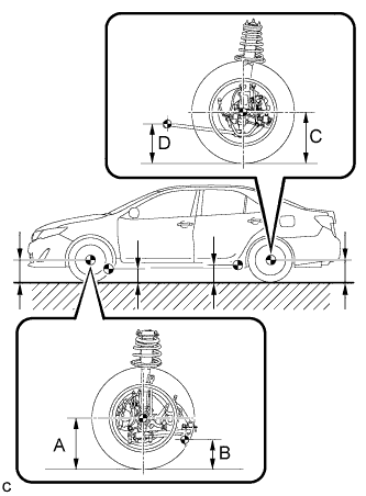
Measure the vehicle height.
-
A: Ground clearance of front wheel center
Measurement points:
-
B: Ground clearance of lower No. 2 suspension arm bushing set bolt center
-
C: Ground clearance of rear wheel center
-
D: Ground clearance of outer strut rod set bolt center
Vehicle Height (Unloaded Vehicle) Front A - B Rear C - D 125 mm (4.92 in.) 55 mm (2.17 in.) -
-
-
INSPECT CAMBER
Note
Inspect while the vehicle is unloaded.
-
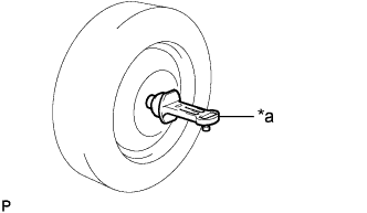
Text in Illustration *a Camber-caster-kingpin Gauge Install a camber-caster-kingpin gauge.
-
Inspect the camber.
Camber (Unloaded Vehicle) Camber Inclination Right-left Difference -1°15' +/- 45' (-1.25° +/- 0.75°) 45' (0.75°) or less Tech Tips
Camber is not adjustable. If the measurement is not within the specified range, inspect the suspension parts for damage and/or wear, and replace them if necessary.
-
-
INSPECT TOE-IN
Note
Inspect while the vehicle is unloaded.
-
Bounce the vehicle up and down at the corners to stabilize the suspension.
-
Release the parking brake and move the shift lever to N.
-
Push the vehicle straight ahead approximately 5 m (16.4 ft.). (Step A)
-
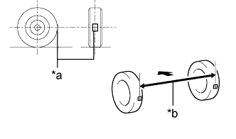
Text in Illustration *a Tread Center Mark *b Dimension B 
Front of the Vehicle Put tread center marks on the rearmost points of the rear wheels and measure the distance between the marks (dimension B).
-
Slowly push the vehicle straight ahead to cause the rear wheels to rotate 180°. Use the rear tire valve as a reference point.
Tech Tips
Do not allow the wheels to rotate more than 180°. If the wheels rotate more than 180°, perform the procedure from Step A again.
-
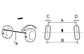
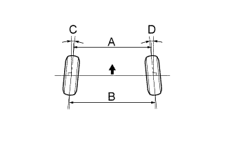
Text in Illustration *a Dimension A Front of the Vehicle Measure the distance between the tread center marks on the front of the rear wheels (dimension A).
Toe-in (Unloaded Vehicle) Specified Condition C + D: 0°13' +/- 0°10' (0.21° +/- 0.17°) B - A: 2.5 +/- 2.0 mm (0.0984 +/- 0.0787 in.) Tech Tips
Measure "B - A" only when "C + D" cannot be measured.
If the toe-in is not within the specified range, adjust it at the rear No. 2 suspension arms.
-
-
ADJUST TOE-IN
-
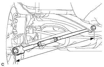
Measure the lengths of the right and left rear No. 2 suspension arms.
Standard Difference 1.5 mm (0.0591 in.) or less -
Loosen the 2 lock nuts.
-
If the length difference between the left and right rear No. 2 suspension arm assemblies is not within the specified range, adjust it by following the procedures below.
-
If the toe-in measurement is greater than the specified range (too much toe-out), extend the shorter rear No. 2 suspension arm by rotating the adjusting tube so that the length difference is within the specified range.
-
If the toe-in measurement is less than the specified range (too much toe-in), shorten the longer rear No. 2 suspension arm by rotating the adjusting tube so that the length difference is within the specified range.
-
Measure the toe-in.
-
-
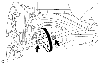
Turn the right and left adjusting tubes by an equal amount to adjust toe-in.
Toe-in (Unloaded Vehicle) Specified Condition C + D: 0°13' +/- 0°10' (0.21° +/- 0.17°) B - A: 2.5 +/- 2.0 mm (0.0984 +/- 0.0787 in.) Text in Illustration Front of the Vehicle Tech Tips
-
Perform adjustments so that the value is as close as possible to the median of the specified range.
-
One turn of each adjusting tube will adjust the toe-in by approximately 11.3 mm (0.445 in.).
-
-
Tighten the lock nuts while securing the adjusting tube in the order indicated below:
-
Tighten the outside lock nut.
-
Tighten the inside lock nut.
-
Retighten the outside lock nut.
- Torque:
- 56 N*m { 570 kgf*cm, 41 ft.*lbf }
-
-