REAR AXLE CARRIER (for TMMK Made) REMOVAL
Tech Tips
-
Use the same procedure for the RH side and LH side.
-
The procedure listed below is for the LH side.
-
REMOVE REAR WHEEL
-
SEPARATE REAR DISC BRAKE CALIPER ASSEMBLY
-
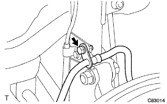
Remove the bolt and separate the rear flexible hose from the rear shock absorber assembly.
-
Remove the 2 bolts, and separate the rear disc brake caliper assembly.
Note
Use wire or an equivalent tool to keep the rear disc brake caliper assembly from hanging down by the rear flexible hose.
-
-
REMOVE PARKING BRAKE SHOE ADJUSTING HOLE PLUG
-
Remove the parking brake shoe adjusting hole plug.
-
-
REMOVE REAR DISC
-
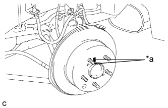
Text in Illustration *a Matchmark Put matchmarks on the rear disc and the rear axle hub.
-
Release the parking brake and remove the rear disc.
Tech Tips
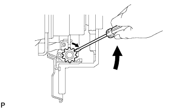
If the disc cannot be removed easily, use a screwdriver to turn the shoe adjuster as shown in the illustration in order to contract the parking brake shoes.
-
-
DISCONNECT SKID CONTROL SENSOR WIRE
-
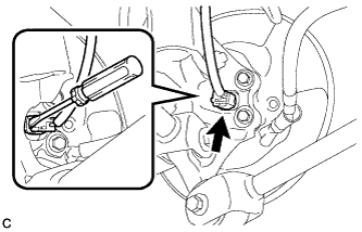
Using a screwdriver, disconnect the connector from the rear speed sensor.
Note
Be careful not to damage the rear speed sensor.
-
-
REMOVE REAR AXLE HUB AND BEARING ASSEMBLY
-
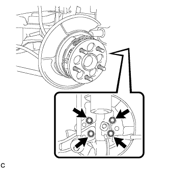
Remove the 4 bolts and the rear axle hub and bearing assembly from the rear axle carrier sub-assembly.
Note
Use wire or an equivalent tool to keep the parking brake assembly from hanging down by the parking brake cable assembly.
-
-
REMOVE REAR HEIGHT CONTROL SENSOR SUB-ASSEMBLY (for RH Side)
-
SEPARATE REAR STRUT ROD ASSEMBLY
-
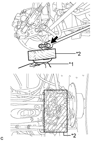
Text in Illustration *1 Jack *2 Wooden Block Use a jack and wooden block to support the rear axle carrier sub-assembly.
-
Remove the bolt, nut and separate the rear strut rod assembly (rear side) from the rear axle carrier sub-assembly.
Note
When removing the bolt, keep the nut from rotating.
-
-
SEPARATE REAR NO. 2 SUSPENSION ARM ASSEMBLY
-
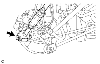
Remove the bolt, nut and separate the rear No. 2 suspension arm assembly (outer side) from the rear axle carrier sub-assembly.
Note
When removing the bolt, keep the nut from rotating.
-
-
SEPARATE REAR NO. 1 SUSPENSION ARM ASSEMBLY
-
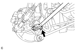
Remove the bolt, nut and separate the rear No. 1 suspension arm assembly (outer side) from the rear axle carrier sub-assembly.
Note
When removing the bolt, keep the nut from rotating.
-
-
REMOVE REAR AXLE CARRIER SUB-ASSEMBLY
-
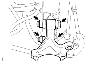
Remove the 2 bolts, 2 nuts and rear axle carrier sub-assembly from the rear shock absorber assembly.
Note
When removing the nuts, keep the bolts from rotating.
-