FRONT LOWER SUSPENSION ARM (for 6AR-FSE) REMOVAL
-
PRECAUTION
Note
After turning the engine switch off, waiting time may be required before disconnecting the cable from the negative (-) battery terminal. Therefore, make sure to read the disconnecting the cable from the negative (-) battery terminal notices before proceeding with work Click here.
-
DISCONNECT CABLE FROM NEGATIVE BATTERY TERMINAL
Note
When disconnecting the cable, some systems need to be initialized after the cable is reconnected Click here.
-
REMOVE FRONT WHEELS
-
REMOVE WINDSHIELD WIPER MOTOR AND LINK ASSEMBLY
-
REMOVE FRONT OUTER COWL TOP PANEL SUB-ASSEMBLY
-
w/ Windshield Deicer System:
-
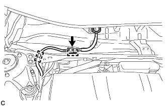
Disengage the 2 clamps.
-
Disconnect the connector and separate the wire harness from the front outer cowl top panel sub-assembly.
-
-
w/ Heated Windshield Defroster System:
-
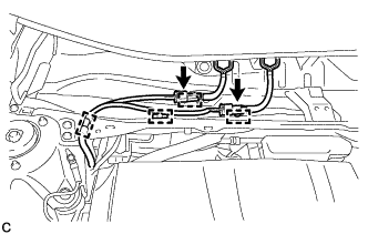
Disengage the 4 clamps.
-
Disconnect the 2 connectors and separate the wire harness from the front outer cowl top panel sub-assembly.
-
-
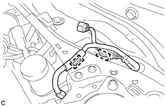
Disengage the 2 clamps and separate the wire harness from the front outer cowl top panel sub-assembly.
-

Remove the 10 bolts and front outer cowl top panel sub-assembly.
-
-
REMOVE NO. 1 ENGINE COVER SUB-ASSEMBLY
-
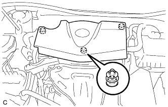
Disengage the 3 grommets to remove the No. 1 engine cover sub-assembly.
Note
When removing the No. 1 engine cover sub-assembly, make sure to lift it upward. Pulling the No. 1 engine cover sub-assembly towards you may damage the No. 1 engine cover sub-assembly.
-
-
REMOVE AIR CLEANER CAP WITH AIR CLEANER HOSE
-
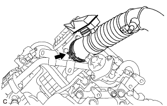
Slide the clip and disconnect the ventilation hose from the cylinder head cover sub-assembly.
-
Disengage the ventilation hose clamp.
-
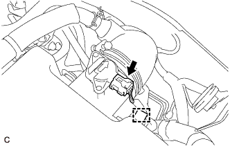
Disconnect the mass air flow meter sub-assembly connector.
-
Disengage the wire harness clamp.
-
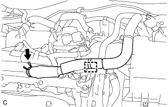
Disconnect the union to connector tube hose from the air cleaner hose sub-assembly.
-
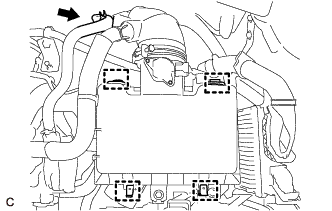
Disengage the 2 air cleaner cap clamps and 2 guides.
-
Loosen the hose clamp and remove the air cleaner cap with air cleaner hose from the throttle body with motor assembly.
-
-
REMOVE AIR CLEANER FILTER ELEMENT SUB-ASSEMBLY
-
Remove the air cleaner filter element sub-assembly from the air cleaner case sub-assembly.
-
-
REMOVE AIR CLEANER CASE SUB-ASSEMBLY
-
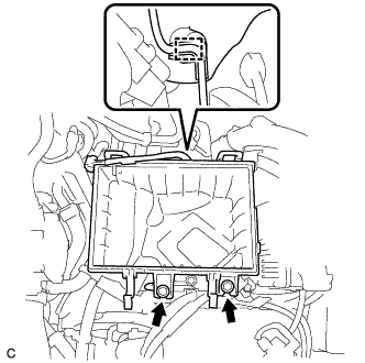
Disconnect the wire harness clamp.
-
Remove the 2 bolts and air cleaner case sub-assembly.
-
-
REMOVE FRONT WHEEL OPENING EXTENSION PAD LH
-
Remove the 3 screws and front wheel opening extension pad LH.
-
-
REMOVE ENGINE UNDER COVER LH
-
Remove the 3 screws, 2 clips and engine under cover LH.
-
-
REMOVE FRONT WHEEL OPENING EXTENSION PAD RH
-
Remove the 3 screws and front wheel opening extension pad RH.
-
-
REMOVE ENGINE UNDER COVER RH
-
Remove the 3 screws, 3 clips and engine under cover RH.
-
-
REMOVE FRONT FENDER APRON SEAL LH (for LH Side)
-
Remove the 2 bolts, clip and front fender apron seal LH.
-
-
REMOVE FRONT FENDER APRON SEAL RH (for RH Side)
-
Remove the 2 bolts, clip and front fender apron seal RH.
-
-
DISCONNECT HEATED OXYGEN SENSOR
-
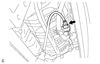
Disconnect the heated oxygen sensor connector.
-
-
SEPARATE FRONT ENGINE MOUNTING INSULATOR
-
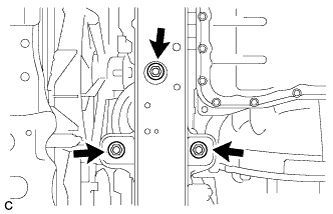
Remove the 3 nuts to separate the front engine mounting insulator from the front frame assembly.
-
-
REMOVE ENGINE MOUNTING INSULATOR LH (for LH Side)
-
Remove the 2 hole plugs.
-
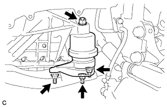
Remove the 4 nuts from the engine mounting insulator LH.
-
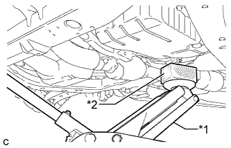
Text in Illustration *1 Jack *2 Wooden Block Using a jack and a wooden block, support the engine assembly with transaxle at the position shown in the illustration. While ensuring that there is no interference from the components surrounding the engine, tilt the engine assembly with transaxle to a position that allows the engine mounting insulator LH to be removed.
Note
-
Do not position the wooden block under the oil pan.
-
Do not damage the components surrounding the engine assembly with transaxle.
-
Tilt the engine assembly with transaxle as little as possible.
-
Ensure that the jack and wooden block are stable.
-
Keep the engine assembly with transaxle supported until installation of the engine mounting insulator LH is complete.
-
-
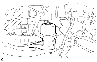
Remove the engine mounting insulator LH from the front frame assembly.
-
-
REMOVE FRONT LOWER NO. 1 SUSPENSION ARM SUB-ASSEMBLY LH (for LH Side)
-
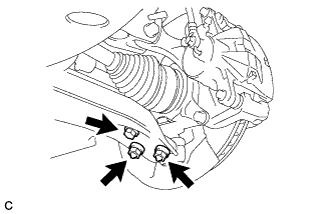
Remove the bolt and 2 nuts, and separate the front lower No. 1 suspension arm sub-assembly LH from the front lower ball joint assembly.
-
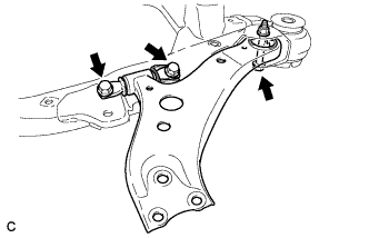
Remove the 3 bolts, nut and front lower No. 1 suspension arm sub-assembly LH from the front frame assembly.
Note
When removing the bolt, keep the nut from rotating.
-
Remove the front lower arm bushing stopper from the front lower No. 1 suspension arm sub-assembly LH.
-
-
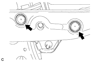
SEPARATE EARTH WIRE (for RH Side)
-
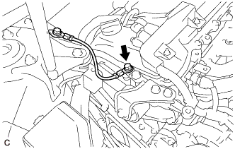
Remove the bolt and earth wire.
-
-
REMOVE NO. 2 ENGINE MOUNTING STAY RH (for RH Side)
-
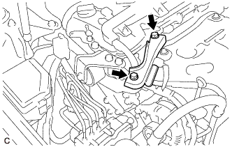
Remove the 2 bolts and No. 2 engine mounting stay RH.
-
-
REMOVE ENGINE MOVING CONTROL ROD BRACKET (for RH Side)
-
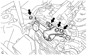
Remove the 4 bolts and engine moving control rod bracket.
-
-
REMOVE ENGINE MOUNTING INSULATOR RH (for RH Side)
-
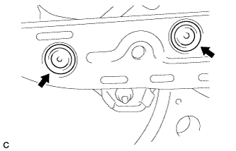
Remove the 2 hole plugs.
-
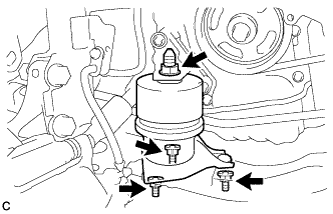
Remove the 4 nuts from the engine mounting insulator RH.
-
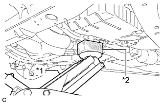
Text in Illustration *1 Jack *2 Wooden Block Using a jack and a wooden block, support the engine assembly with transaxle at the position shown in the illustration. While ensuring that there is no interference from the components surrounding the engine, tilt the engine assembly with transaxle to a position that allows the engine mounting insulator RH to be removed.
Note
-
Do not position the wooden block under the oil pan.
-
Do not damage the components surrounding the engine assembly with transaxle.
-
Tilt the engine assembly with transaxle as little as possible.
-
Ensure that the jack and wooden block are stable.
-
Keep the engine assembly with transaxle supported until installation of the engine mounting insulator RH is complete.
-
-
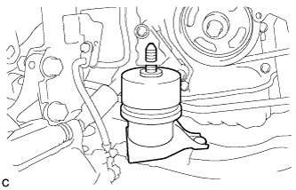
Remove the engine mounting insulator RH from the front frame assembly.
-
-
REMOVE FRONT LOWER NO. 1 SUSPENSION ARM SUB-ASSEMBLY RH (for RH Side)
-
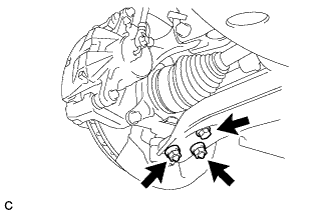
Remove the bolt and 2 nuts, and separate the front lower No. 1 suspension arm sub-assembly RH from the front lower ball joint assembly.
-
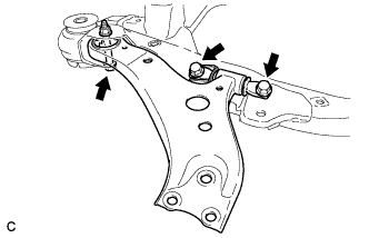
Remove the 3 bolts, nut and front lower No. 1 suspension arm sub-assembly RH from the front frame assembly.
Note
When removing the bolt, keep the nut from rotating.
-
Remove the front lower arm bushing stopper from the front lower No. 1 suspension arm sub-assembly RH.
-