FRONT DRIVE SHAFT ASSEMBLY (for 2AR-FE) REMOVAL

Tech Tips
-
Use the same procedure for the RH side and LH side.
-
The following procedure is for the LH side.
-
REMOVE FRONT WHEELS
-
REMOVE FRONT WHEEL OPENING EXTENSION PAD LH
-
REMOVE ENGINE UNDER COVER LH
-
REMOVE FRONT WHEEL OPENING EXTENSION PAD RH
-
REMOVE ENGINE UNDER COVER RH
-
REMOVE FRONT FENDER APRON SEAL LH
-
REMOVE FRONT FENDER APRON SEAL RH
-
DRAIN AUTOMATIC TRANSAXLE FLUID
-
Remove the front wheel opening extension pad LH, engine under cover LH and front fender apron seal LH.
-
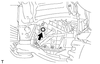
Remove the refill plug and gasket from the automatic transaxle assembly.
-
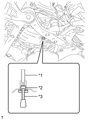
Text in Illustration *1 No. 1 Transmission Oil Filler Tube *2 Overflow Plug *3 Hexagon Socket Wrench Using a 6 mm hexagon socket wrench, remove the overflow plug and gasket from the automatic transaxle assembly.
-
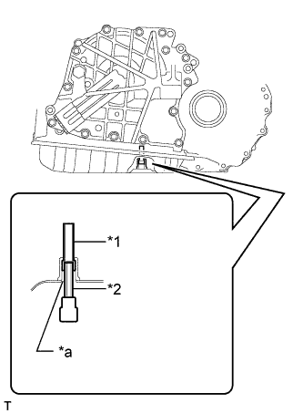
Text in Illustration *1 No. 1 Transmission Oil Filler Tube *2 Hexagon Socket Wrench *a Overflow Plug Hole Using a 6 mm hexagon socket wrench, remove the No. 1 transmission oil filler tube from the automatic transaxle assembly.
-
Drain automatic transaxle fluid from the automatic transaxle assembly.
-
Text in Illustration *1 No. 1 Transmission Oil Filler Tube *2 Hexagon Socket Wrench *a Overflow Plug Hole Using a 6 mm hexagon socket wrench, install the No. 1 transmission oil filler tube to the automatic transaxle assembly.
- Torque:
- 0.8 N*m { 8 kgf*cm, 7 in.*lbf }
-
Text in Illustration *1 No. 1 Transmission Oil Filler Tube *2 Overflow Plug *3 Hexagon Socket Wrench Using a 6 mm hexagon socket wrench, install a new gasket and the overflow plug to the automatic transaxle assembly.
- Torque:
- 40 N*m { 408 kgf*cm, 29 ft.*lbf }
-
Install a new gasket and the refill plug to the automatic transaxle assembly.
- Torque:
- 49 N*m { 500 kgf*cm, 36 ft.*lbf }
-
-
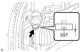
REMOVE FRONT AXLE SHAFT NUT
-
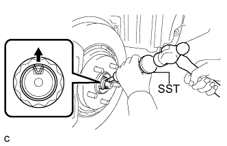
Using SST and a hammer, release the staked part of the front axle shaft nut.
- SST
- 09930-00010
Note
Loosen the staked part of the nut completely, otherwise the threads of the drive shaft may be damaged.
-
While applying the brakes, remove the front axle shaft nut.
-
-
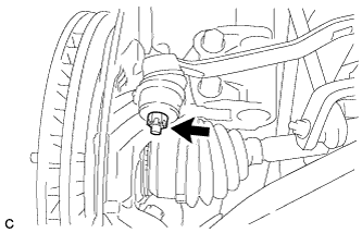
SEPARATE FRONT STABILIZER LINK ASSEMBLY
-
for Steel Type:
-
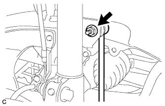
Remove the nut and separate the front stabilizer link assembly from the front shock absorber assembly.
If the ball joint turns together with the nut, use a hexagon wrench to hold the stud bolt.
-
-
for Aluminum Type:
-
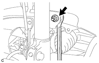
Remove the nut and separate the front stabilizer link assembly from the front shock absorber assembly.
If the ball joint turns together with the nut, use a wrench to hold the stud bolt.
-
-
-
SEPARATE FRONT SPEED SENSOR
-
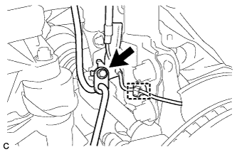
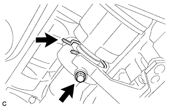
Remove the bolt, disengage the clamp and separate the front speed sensor and front flexible hose.
Note
Be sure to separate the front speed sensor from the front shock absorber assembly completely.
-
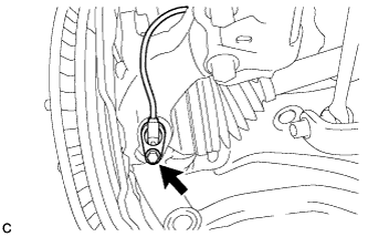
Remove the bolt and front speed sensor from the steering knuckle.
Note
-
Prevent foreign matter from contacting the sensor tip.
-
Be careful not to damage the front speed sensor.
-
Clean the speed sensor installation hole and the contact surfaces every time the speed sensor is removed.
-
-
-
SEPARATE TIE ROD ASSEMBLY
-
Remove the cotter pin and nut.
-
Install SST to the tie rod assembly LH.
- SST
- 09960-20010 ( 09961-02060 )
Note
Make sure that the lower ends of the tie rod assembly LH and SST are aligned.
-
Secure SST using a string.
Note
Be sure to tighten the string firmly to secure SST to the steering knuckle to prevent SST from falling off.
-
Using SST, separate the tie rod assembly LH from the steering knuckle.
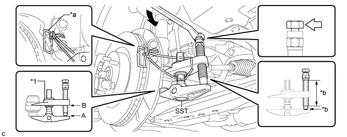
Text in Illustration *1 Center Nut - - *a String *b Grease Application Area 
Place the wrench here. - - - SST
- 09960-20010 ( 09961-02010 )
CAUTION:
Apply grease to the bolt threads and the tip of SST.
Note
-
Install SST with the center nut so that A and B shown in the illustration are parallel. Otherwise, the dust cover may be damaged.
-
Be sure to place the wrench on the part indicated in the illustration.
-
Do not damage the front disc brake dust cover.
-
Do not damage the ball joint dust cover.
-
Do not damage the steering knuckle.
-
-
SEPARATE FRONT LOWER NO. 1 SUSPENSION ARM SUB-ASSEMBLY
-
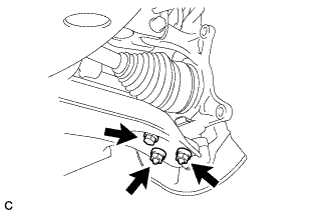
Remove the bolt and 2 nuts, and separate the front lower No. 1 suspension arm sub-assembly from the front lower ball joint assembly.
-
-
SEPARATE FRONT DRIVE SHAFT ASSEMBLY
-
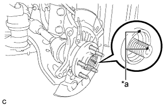
Text in Illustration *a Matchmark Put matchmarks on the front drive shaft assembly and the front axle hub sub-assembly.
-
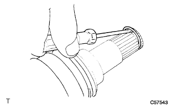
Using a plastic hammer, separate the front drive shaft assembly from the front axle assembly.
If it is difficult to separate, tap the end of the front drive shaft assembly using a brass bar and a hammer.
-
-
REMOVE FRONT DRIVE SHAFT ASSEMBLY LH
-
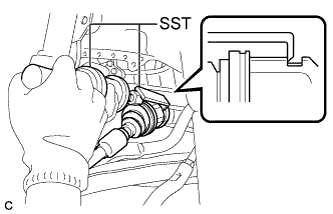
Using SST, remove the front drive shaft assembly LH.
- SST
- 09520-00031
- 09520-01010
Note
-
Do not damage the transaxle case oil seal.
-
Do not damage the front axle inboard joint boot.
-
Do not drop the front drive shaft assembly LH.
-
-
REMOVE FRONT DRIVE SHAFT ASSEMBLY RH
-
Separate the bearing bracket hole snap ring from the drive shaft bearing bracket.
-
Remove the bolt and front drive shaft assembly RH from the drive shaft bearing bracket.
Note
-
Do not damage the front transaxle case oil seal.
-
Do not damage the front axle inboard joint boot.
-
Do not drop the front drive shaft assembly RH.
-
-
Remove the bearing bracket hole snap ring from the front drive shaft assembly RH.
-
-
REMOVE FRONT DRIVE SHAFT HOLE SNAP RING LH
-
Using a screwdriver, remove the front drive shaft hole snap ring LH.
-