DIFFERENTIAL CASE REASSEMBLY

-
INSTALL FRONT DIFFERENTIAL SIDE GEAR
-
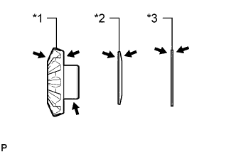
Text in Illustration *1 Front Differential Side Gear *2 Conical Spring *3 Front No. 1 Differential Side Gear Thrust Washer 
ATF Coat the 2 front differential side gears, 2 front No. 1 differential side gear thrust washers and 2 conical springs with ATF.
-
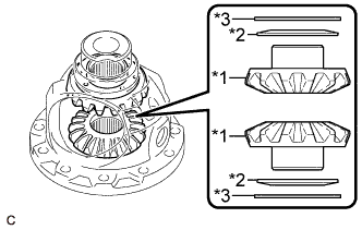
Text in Illustration *1 Front Differential Side Gear *2 Conical Spring *3 Front No. 1 Differential Side Gear Thrust Washer Install the 2 front differential side gears, 2 front No. 1 differential side gear thrust washers and 2 conical springs to the front differential case.
Note
-
Do not drop the front differential side gears, front No. 1 differential side gear thrust washers or conical springs.
-
Make sure that the conical springs are installed with the correct orientation.
-
-
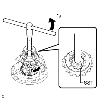
Install SST as shown in the illustration and tighten it.
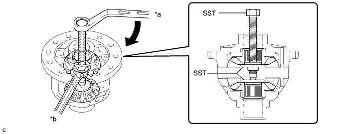
Text in Illustration *a Turn *b Hold - SST
- 09528-52010 ( 09528-05010, 09953-05010 )
Note
Do not overtighten SST, as doing so will damage the front differential side gears, conical springs, front No. 1 differential side gear thrust washers and front differential case.
Tech Tips
-
Tighten SST to create the necessary clearance to install the front differential pinions.
-
When installing the front differential pinions, do not overtighten SST, as it is necessary to rotate the front differential side gears.
-
Coat the 2 front differential pinions and 2 front differential pinion thrust washers with ATF.
Text in Illustration ATF -
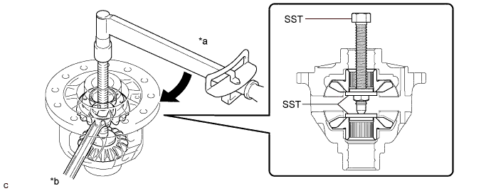
Text in Illustration *a Turn Using SST as shown in the illustration, rotate the front differential side gear and install the 2 front differential pinions and 2 front differential pinion thrust washers to the front differential case.
- SST
- 09528-52010 ( 09528-05030 )
CAUTION:
Be careful not to pinch your fingers between the front differential pinion and front differential case.
Note
Do not drop the front differential pinions or front differential pinion thrust washers.
-
-
INSPECT FRONT DIFFERENTIAL PINION BACKLASH
-
Install SST as shown in the illustration and tighten it.
Text in Illustration *a Turn *b Hold - SST
- 09528-52010 ( 09528-05010, 09953-05010 )
- Torque:
- 10 N*m { 102 kgf*cm, 7 ft.*lbf }
-
Secure the front differential case with front differential ring gear in a vise between aluminum plates.
Note
Do not overtighten the vise.
-
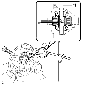
Text in Illustration *1 Front No. 1 Differential Pinion Shaft Install the front No. 1 differential pinion shaft to the front differential pinion as shown in the illustration.
-
Using a dial indicator, measure the front differential pinion backlash.
Standard Backlash 0.20 mm (0.00787 in.) or less If the backlash is not as specified, replace the front No. 1 differential side gear thrust washers with washers of a different thickness. Use the table below to select front No. 1 differential side gear thrust washers which will ensure that the backlash is within the specification.
Tech Tips
Select front No. 1 differential side gear thrust washers of the same thickness for both the right and left side.
Front No. 1 Differential Side Gear Thrust Washer Thickness: Part No. Thickness (mm (in.)) 41361-73050 0.90 (0.0354) 41361-73010 1.00 (0.0394) 41361-73020 1.10 (0.0433) 41361-73030 1.20 (0.0472)
-
-
INSTALL FRONT NO. 1 DIFFERENTIAL PINION SHAFT
-
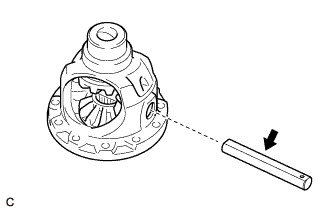
Coat the front No. 1 differential pinion shaft with ATF.
Text in Illustration ATF -
Install the front No. 1 differential pinion shaft to the front differential case so that the hole for the front differential pinion shaft straight pin is aligned with the hole in the front differential case.
-
-
INSPECT FRONT DIFFERENTIAL CASE
-
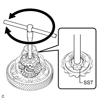
Using SST, rotate the front differential side gear as shown in the illustration.
- SST
- 09528-52010 ( 09528-05030 )
Standard The front differential side gear does not lock when rotated in either direction.
-
If the front differential side gear locks, perform all of the following inspections.
-
If the front differential side gear still locks after replacing the malfunctioning parts, replace the front differential case.
-
Replace any parts that do not meet the specifications.
-
-
INSTALL FRONT DIFFERENTIAL PINION SHAFT STRAIGHT PIN
-
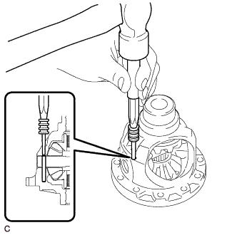
Using a 5 mm pin punch and a hammer, install the front differential pinion shaft straight pin to the front differential case.
-
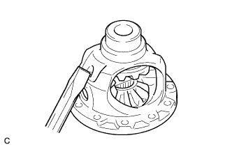
Using a chisel and a hammer, stake the front differential case.
-
-
INSTALL FRONT DIFFERENTIAL RING GEAR
-
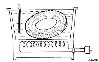
Using ATF and a heater, heat the front differential ring gear to 90 to 110°C (194 to 230°F).
Note
Do not heat the front differential ring gear to more than 110°C (230°F).
-
Clean the contact surface of the front differential case.
-
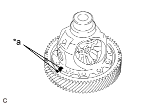
Text in Illustration *a Matchmark Align the matchmarks, and install the front differential ring gear to the front differential case quickly.
-
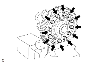
Install the 12 bolts.
- Torque:
- 120 N*m { 1224 kgf*cm, 89 ft.*lbf }
Note
-
Tighten the bolts after the front differential ring gear has cooled down sufficiently.
-
Tighten the bolts evenly in a diagonal pattern using several steps.
-