AUTOMATIC TRANSAXLE UNIT INSPECTION
-
INSPECT TRANSMISSION OIL CLEANER MAGNET
-
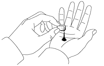
Use the removed transmission oil cleaner magnets to collect any steel chips. Examine the chips and particles in the automatic transaxle oil pan sub-assembly and on the transmission oil cleaner magnets to determine what type of wear might be found in the automatic transaxle assembly.
Result Steel (magnetic) Brass (non-magnetic) Bearing, gear and plate wear Bushing wear
-
-
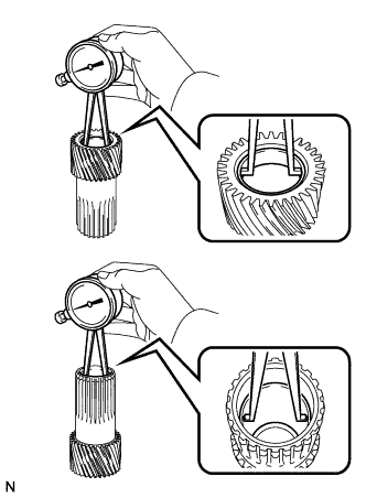
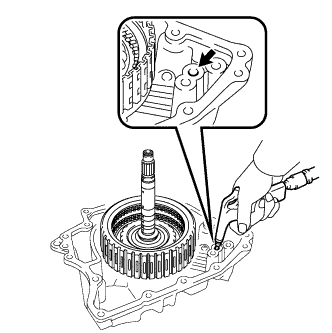
INSPECT INPUT SHAFT SUB-ASSEMBLY END PLAY
-
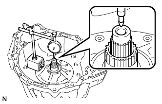
Using a dial indicator, measure the input shaft sub-assembly end play.
Standard End Play 0.020 to 1.242 mm (0.000787 to 0.0489 in.)
-
-
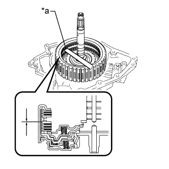
INSPECT INTERMEDIATE SHAFT END PLAY
-
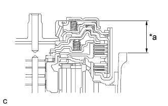
Text in Illustration *a Dimension (A) Clean the contact surfaces of the transaxle case sub-assembly and rear transaxle cover sub-assembly.
-
Place a straightedge on the multiple direct clutch drum and measure the distance between the transaxle case sub-assembly and the straightedge (Dimension (A)) using a vernier caliper.
-
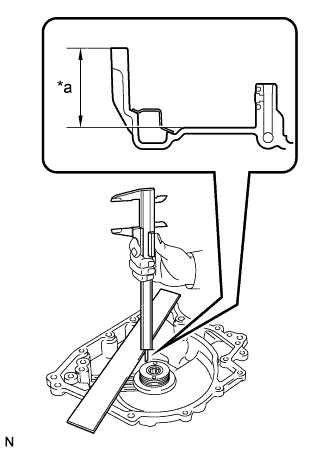
Text in Illustration *a Dimension (B) Using a vernier caliper and a straightedge, measure the distance shown in the illustration (Dimension (B)).
-
Calculate the end play using the following formula:
End play = Dimension (B) - Dimension (A) - Thrust needle roller bearing thickness
Standard End Play 0.022 to 1.099 mm (0.000866 to 0.0433 in.)
-
-
INSPECT PLANETARY SUN GEAR SUB-ASSEMBLY
-
Using a caliper gauge, measure the inside diameters of the bushings of the planetary sun gear sub-assembly.
Standard Inside Diameter 25.525 to 25.546 mm (1.00492 to 1.00575 in.) Maximum Inside Diameter 25.546 mm (1.00575 in.) If the inside diameter is greater than the maximum, replace the planetary sun gear sub-assembly.
-
-
INSPECT REAR PLANETARY SUN GEAR ASSEMBLY
-
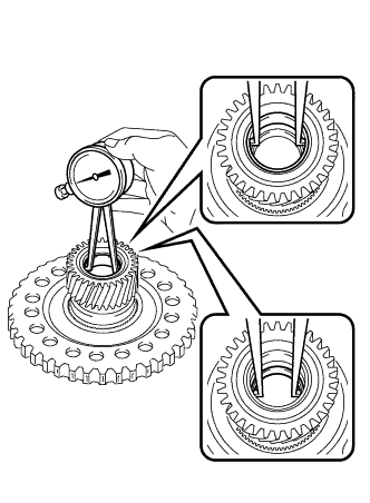
Using a caliper gauge, measure the inside diameter of the bushing of the rear planetary sun gear assembly.
Standard Inside Diameter 25.580 to 25.601 mm (1.00708 to 1.00791 in.) Maximum Inside Diameter 25.601 mm (1.00791 in.) If the inside diameter is greater than the maximum, replace the rear planetary sun gear assembly.
-
-
INSPECT UNDERDRIVE PLANETARY GEAR ASSEMBLY
-
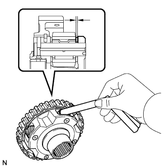
Using a feeler gauge, measure the clearance between the underdrive planetary gear case and each pinion gear.
Standard Clearance 0.18 to 0.54 mm (0.00709 to 0.0213 in.) If the clearance is not as specified, replace the underdrive planetary gear assembly.
-
-
INSPECT ONE-WAY CLUTCH ASSEMBLY
-
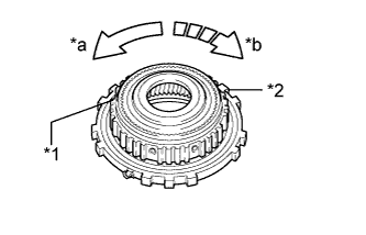
Text in Illustration *1 Planetary Ring Gear *2 One-way Clutch Assembly *a Free *b Lock Temporarily install the one-way clutch assembly to the planetary ring gear.
-
Make sure that the one-way clutch assembly turns freely counterclockwise and locks when turned clockwise.
If the one-way clutch assembly does not operate normally, replace it.
-
-
INSPECT NO. 1 BRAKE DISC
-
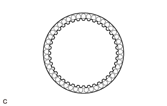
Check if the contact surfaces of the No. 1 brake discs, No. 1 brake plates and No. 1 brake flange are worn or burnt.
If necessary, replace them.
Note
-
If the lining of any No. 1 brake disc is peeled off or discolored, or even if part of the groove is damaged, replace all of the No. 1 brake discs.
-
Before installing new No. 1 brake discs, soak them in ATF for at least 15 minutes.
-
-
-
INSPECT NO. 2 BRAKE DISC
-
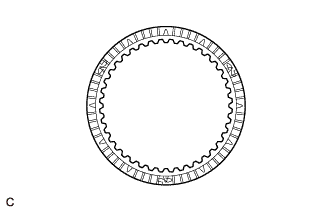
Check if the contact surfaces of the No. 2 brake discs, No. 2 brake plates and No. 2 brake flange are worn or burnt.
If necessary, replace them.
Note
-
If the lining of any No. 2 brake disc is peeled off or discolored, or even if part of the groove is damaged, replace all of the No. 2 brake discs.
-
Before installing new No. 2 brake discs, soak them in ATF for at least 15 minutes.
-
-
-
INSPECT NO. 3 BRAKE DISC
-
Check if the contact surfaces of the No. 3 brake discs, No. 3 brake plates and No. 3 brake flanges are worn or burnt.
If necessary, replace them.
Note
-
If the lining of any No. 3 brake disc is peeled off or discolored, or even if part of the groove is damaged, replace all of the No. 3 brake discs.
-
Before installing new No. 3 brake discs, soak them in ATF for at least 15 minutes.
-
-
-
INSPECT 2ND BRAKE PISTON RETURN SPRING SUB-ASSEMBLY
-
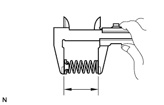
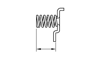
Using a vernier caliper, measure the free length of the 3 2nd brake piston return spring sub-assemblies including the spring seats.
Standard Free Length 23.26 mm (0.916 in.) If the free length is shorter than the standard free length, replace the 2nd brake piston return spring sub-assembly.
-
-
INSPECT 1ST AND REVERSE BRAKE RETURN SPRING SUB-ASSEMBLY
-
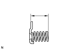
Using a vernier caliper, measure the free length of the 1st and reverse brake return spring sub-assembly including the spring seat.
Standard Free Length 15.79 mm (0.622 in.) If the free length is shorter than the standard free length, replace the 1st and reverse brake return spring sub-assembly.
-
-
INSPECT NO. 3 BRAKE PISTON RETURN SPRING SUB-ASSEMBLY
-
Using a vernier caliper, measure the free length of the No. 3 brake piston return spring sub-assembly including the spring seat.
Standard Free Length 9.15 mm (0.360 in.) If the free length is shorter than the standard free length, replace the No. 3 brake piston return spring sub-assembly.
-
-
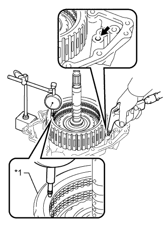
INSPECT CLEARANCE OF NO. 1 BRAKE PISTON
-
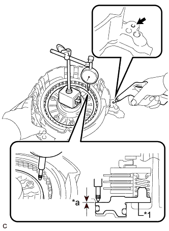
Text in Illustration *1 No. 1 Brake Piston *a Clearance Apply compressed air to the oil hole shown in the illustration, and check the operation of the No. 1 brake piston.
-
Set a dial indicator as shown in the illustration.
-
Using the dial indicator, measure the clearance of the No. 1 brake piston while applying compressed air (350 kPa 3.6 kgf/cm2, 51 psi).
Standard Clearance 0.729 to 0.951 mm (0.0287 to 0.0374 in.) Tech Tips
Measure the clearance at 3 points where the No. 1 brake piston diameter is approximately 140 mm (5.51 in.) and calculate the average.
If the clearance is not as specified, select an appropriate No. 1 brake flange so that the clearance will be within the specified range.
Tech Tips
There are 6 No. 1 brake flanges of different thicknesses.
No. 1 Brake Flange Thickness Part No. Mark Thickness
(mm (in.))
35676-73010 30 3.0 (0.118) 35676-73020 31 3.1 (0.122) 35676-73030 32 3.2 (0.126) 35676-73040 33 3.3 (0.130) 35676-73050 34 3.4 (0.134) 35676-73060 35 3.5 (0.138)
-
-
INSPECT CLEARANCE OF NO. 2 BRAKE PISTON
-
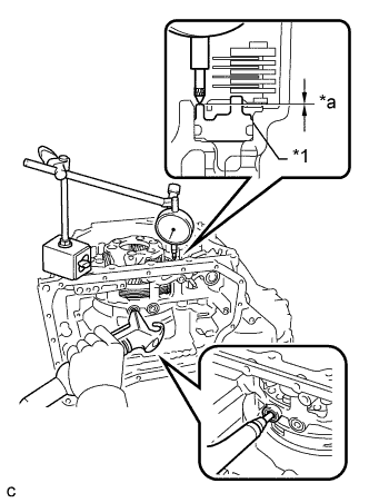
Text in Illustration *1 No. 2 Brake Piston *a Clearance Apply compressed air to the oil hole shown in the illustration, and check the operation of the No. 2 brake piston.
-
Set a dial indicator as shown in the illustration.
-
Using the dial indicator, measure the clearance of the No. 2 brake piston while applying compressed air (350 kPa 3.6 kgf/cm2, 51 psi).
Standard Clearance 0.966 to 1.234 mm (0.0380 to 0.0486 in.) Tech Tips
Measure the clearance at 3 points where the No. 2 brake piston diameter is approximately 140 mm (5.51 in.) and calculate the average.
If the clearance is not as specified, select an appropriate No. 2 brake flange so that the clearance will be within the specified range.
Tech Tips
There are 5 No. 2 brake flanges of different thicknesses.
No. 2 Brake Flange Thickness Part No. Mark Thickness
(mm (in.))
35678-33140 40A 4.0 (0.157) 35678-33150 41A 4.1 (0.161) 35678-33160 42A 4.2 (0.165) 35678-33170 43A 4.3 (0.169) 35678-33180 44A 4.4 (0.173)
-
-
INSPECT CLEARANCE OF NO. 3 BRAKE PISTON
-
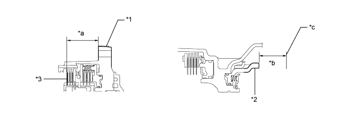
Using a vernier caliper and a straightedge, measure the distance shown in the illustration (Dimension (A)) while a load of 500 N (51 kgf, 112.4 lbf) is being applied to the No. 3 brake flange.
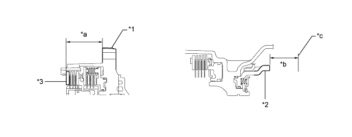
Text in Illustration *1 Front Oil Pump Assembly *2 No. 3 Brake Piston *3 No. 3 Brake Flange - - *a Dimension (A) *b Dimension (B) *c Contact Surface of Front Oil Pump Assembly - - Tech Tips
Measure the distance (Dimension(A)) at 3 points where the No. 3 brake flange diameter is approximately 166 mm (6.54 in.) and calculate the average.
-
Using a vernier caliper and a straightedge, measure the distance shown in the illustration (Dimension (B)).
Tech Tips
Measure the distance (Dimension(B)) at 3 points where the No. 3 brake piston diameter is approximately 166 mm (6.54 in.) and calculate the average.
-
Calculate the clearance using the following formula:
Clearance = Dimension (B) - Dimension (A)
Standard Clearance 0.727 to 0.927 mm (0.0286 to 0.0365 in.) If the clearance is not as specified, select an appropriate No. 3 brake flange so that the clearance will be within the specified range.
-
Adjust clearance of No. 3 brake piston:
-
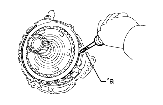
Text in Illustration *a Protective Tape Using a screwdriver with its tip wrapped with protective tape, remove the snap ring from the front oil pump assembly.
-
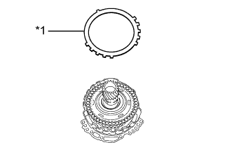
Text in Illustration *1 No. 3 Brake Flange Remove the No. 3 brake flange from the front oil pump assembly.
-
Using a vernier caliper and a straightedge, measure the distance shown in the illustration (Dimension (A)) while a load of 500 N (51 kgf, 112.4 lbf) is being applied to the No. 3 brake disc.
Text in Illustration *1 Front Oil Pump Assembly *2 No. 3 Brake Piston *3 No. 3 Brake Disc - - *a Dimension (A) *b Dimension (B) *c Contact Surface of Front Oil Pump Assembly - - Tech Tips
Measure the distance (Dimension(A)) at 3 points where the No. 3 brake disc diameter is approximately 166 mm (6.54 in.) and calculate the average.
-
Using a vernier caliper and a straightedge, measure the distance shown in the illustration (Dimension (B)).
Tech Tips
Measure the distance (Dimension(B)) at 3 points where the No. 3 brake piston diameter is approximately 166 mm (6.54 in.) and calculate the average.
-
Calculate the thickness of the replacement No. 3 brake flange using the following formula:
Thickness of Replacement No. 3 Brake Flange Dimension (B) - Dimension (A) - (0.727 to 0.927 mm (0.0286 to 0.0365 in.)) Tech Tips
There are 6 No. 3 brake flanges of different thicknesses.
No. 3 Brake Flange Thickness Part No. Mark Thickness
(mm (in.))
35679-73020 38 3.8 (0.150) 35679-73030 39 3.9 (0.154) 35679-73040 40 4.0 (0.157) 35679-73050 41 4.1 (0.161) 35679-73060 42 4.2 (0.165) 35679-73070 43 4.3 (0.169) 35679-73080 44 4.4 (0.173) -
Text in Illustration *1 No. 3 Brake Flange Install the No. 3 brake flange to the front oil pump assembly.
-
Using a screwdriver with its tip wrapped with protective tape, install the snap ring to the front oil pump assembly.
Note
-
Confirm that the snap ring is correctly located in the groove of the front oil pump assembly.
-
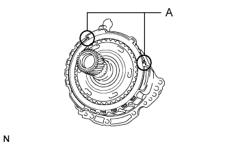
Make sure that the snap ring ends are positioned as shown in the illustration (A).
-
-
-
-
INSPECT CLEARANCE OF NO. 1 CLUTCH
-
Install the rear multiple disc clutch assembly to the rear transaxle cover sub-assembly.
-
Check that the piston moves when compressed air (200 kPa, 2.0 kgf/cm2, 29 psi) is applied to the oil hole.
-
Text in Illustration *a Feeler Gauge Using a feeler gauge, measure the No. 1 clutch pack clearance.
Standard Pack Clearance 0.601 to 0.819 mm (0.0237 to 0.0322 in.) Tech Tips
Measure the clearance at 3 points where the flange diameter is approximately 152 mm (5.98 in.) and calculate the average.
If the pack clearance is not as specified, replace the rear multiple disc clutch assembly.
-
-
INSPECT CLEARANCE OF NO. 2 CLUTCH
-
Install the rear multiple disc clutch assembly to the rear transaxle cover sub-assembly.
-
Text in Illustration *1 No. 2 Direct Clutch Piston Using a dial indicator, measure the No. 2 clutch pack clearance while applying compressed air (200 kPa, 2.0 kgf/cm2, 29 psi).
Standard Pack Clearance 0.394 to 0.605 mm (0.0155 to 0.0238 in.) Tech Tips
Measure the clearance at 3 points where the diameter of the No. 2 direct clutch piston is approximately 152 mm (5.98 in.) and calculate the average.
If the pack clearance is not as specified, replace the rear multiple disc clutch assembly.
-