AUTOMATIC TRANSAXLE ASSEMBLY REMOVAL
CAUTION:
The engine assembly with automatic transaxle assembly is very heavy. Be sure to follow the procedure described in the repair manual, or the engine lifter may suddenly drop.
Note
If automatic transmission parts are replaced, refer to the Parts Replacement Compensation Table to determine if any additional operations are necessary Click here.
-
REMOVE FLYWHEEL HOUSING UNDER COVER
-
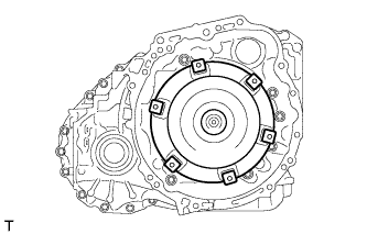
REMOVE DRIVE PLATE AND TORQUE CONVERTER ASSEMBLY SETTING BOLT
-
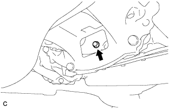
Turn the crankshaft to gain access to the removable locations of the 6 drive plate and torque converter assembly setting bolts and remove each drive plate and torque converter assembly setting bolt while holding the crankshaft pulley bolt with a wrench.
Tech Tips
There will be one black colored drive plate and torque converter assembly setting bolt.
-
-
REMOVE ENGINE ASSEMBLY WITH TRANSAXLE
-
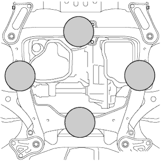
Place height adjustment attachments and plate lift attachments in the positions shown in the illustration and set an engine lifter underneath the engine assembly with transaxle.
Text in Illustration 
Attachment Installation Position Note
-
Using height adjustment attachments and plate lift attachments, place the engine assembly with transaxle horizontally.
-
Securely support the engine assembly to prevent it from turning upside down until it is secured to an engine stand.
-
To prevent the oil pan sub-assembly from deforming, do not place any attachments under the oil pan sub-assembly of the engine assembly with transaxle.
-
Do not perform any procedures while the engine assembly is suspended because doing so may cause the engine assembly to drop, resulting in injury. However, the engine assembly needs to be suspended when it is installed to or removed from an engine stand.
-
-
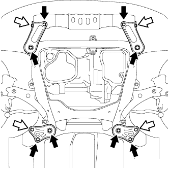
Remove the 4 bolts, 2 nuts, frame side rail plate sub-assembly RH and frame side rail plate sub-assembly LH.
Text in Illustration 
Bolt 
Nut -
Remove the 4 bolts, 2 nuts, front suspension member bracket sub-assembly RH and front suspension member bracket sub-assembly LH.
-
Operate the engine lifter and remove the engine assembly with transaxle from the vehicle.
Note
-
Make sure that the engine assembly with transaxle is clear of all wiring and hoses.
-
While lowering the engine assembly with transaxle from the vehicle, do not allow it to contact the vehicle.
-
-
-
INSTALL ENGINE HANGERS
-
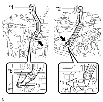
Text in Illustration *1 No. 1 Engine Hanger *2 No. 2 Engine Hanger *a Stopper *b Rib Install the No. 1 engine hanger with the bolt as shown in the illustration.
- Torque:
- 43 N*m { 438 kgf*cm, 32 ft.*lbf }
Note
Make sure to install the No. 1 engine hanger with the stopper contacting the rib of the cylinder head sub-assembly as shown in the illustration.
Tech Tips
Item Part No. No. 1 Engine Hanger 12281-0V010 No. 2 Engine Hanger 12282-0V010 Bolt 90105-C0170 -
Install the No. 2 engine hanger with the bolt as shown in the illustration.
- Torque:
- 43 N*m { 438 kgf*cm, 32 ft.*lbf }
Note
Make sure to install the No. 2 engine hanger with the stopper positioned between the ribs of the cylinder head sub-assembly as shown in the illustration.
-
Using an engine sling device and engine lift, secure the engine assembly with transaxle.
Note
-
Adjust the angle of the sling device carefully to prevent the engine assembly or engine hangers from deforming or becoming damaged.
-
Do not perform any procedures while the engine assembly is suspended because doing so may cause the engine assembly to drop, resulting in injury. However, the engine assembly needs to be suspended when it is installed to or removed from an engine stand.
-
-
-
REMOVE FRONT FRAME ASSEMBLY
-
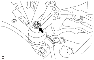
Remove the nut and separate the engine mounting insulator LH.
-
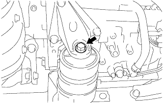
Remove the bolt and separate the front engine mounting insulator.
-
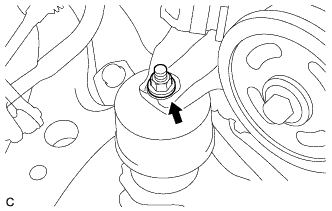
Remove the nut and separate the engine mounting insulator RH.
-
Remove the front frame assembly.
-
Using height adjustment attachments and plate lift attachments, place the engine assembly with transaxle on a flat level surface.
Note
-
Using height adjustment attachments and plate lift attachments, place the engine assembly with transaxle horizontally.
-
To prevent the oil pan sub-assembly from deforming, do not place any attachments under the oil pan sub-assembly of the engine assembly with transaxle.
-
-
-
REMOVE WIRING HARNESS CONNECTOR
-
Disengage the wire harness clamp.
-
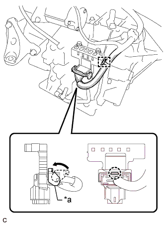
Text in Illustration *a Lever Disengage the claw, push up the lever and disconnect the connector of the wiring harness connector.
-
Remove the 2 bolts and wiring harness connector from the transaxle case sub-assembly.
-
-
REMOVE WIRE HARNESS CLAMP BRACKET
-
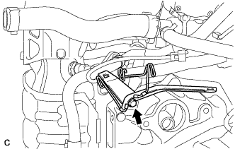
Disconnect the transmission breather hose sub-assembly from the clamp.
-
Remove the clamp from the wire harness clamp bracket.
-
Disconnect the oxygen sensor connector.
-
Disengage the 4 clamps to disconnect the wire harness from the wire harness clamp bracket.
-
Remove the bolt and wire harness clamp bracket from the transaxle housing.
-
-
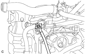
DISCONNECT ENGINE WIRE
-
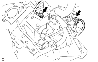
Remove the bolt and disconnect the ground cable from the transaxle case sub-assembly.
-
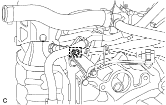
Disconnect the park/neutral position switch assembly connector.
-
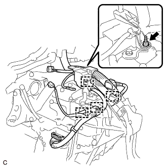
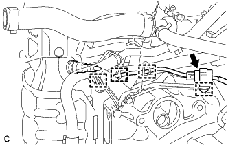
Remove the nut from the wire harness clamp bracket.
-
Disengage the 4 clamps to disconnect the engine wire from the transaxle case sub-assembly.
-
-
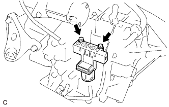
REMOVE FRONT ENGINE MOUNTING BRACKET
-
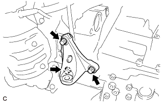
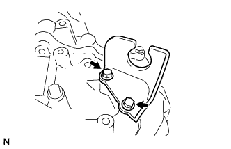
Remove the 3 bolts and front engine mounting bracket from the transaxle housing.
-
-
REMOVE AUTOMATIC TRANSAXLE ASSEMBLY
-
Support the automatic transaxle assembly with a transmission jack.
Note
-
In order to protect the automatic transaxle oil pan sub-assembly, place attachments on the transmission jack.
-
Make sure that the attachments and automatic transaxle oil pan sub-assembly are centered on the transmission jack.
-
To prevent the automatic transaxle oil pan sub-assembly from being deformed, do not place any attachments under the automatic transaxle oil pan sub-assembly.
-
Hold the engine assembly with a suitable adapter, such as a rope, during the operation.
-
-
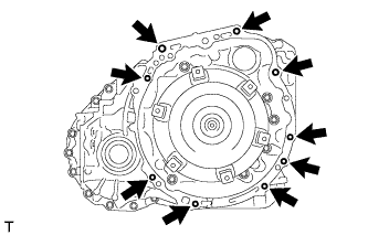
Remove the 9 bolts and automatic transaxle assembly from the engine assembly.
Note
-
Secure the automatic transaxle assembly to the transmission jack using a belt, etc. to prevent it from falling.
-
To prevent damage to the knock pins, do not pry between the automatic transaxle assembly and engine assembly.
-
-
-
REMOVE NO. 1 TRANSMISSION CONTROL CABLE BRACKET
-
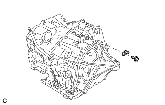
Remove the 2 bolts and No. 1 transmission control cable bracket from the transaxle case sub-assembly.
-
-
REMOVE WIRE HARNESS CLAMP BRACKET
-
Remove the bolt and wire harness clamp bracket from the rear transaxle cover sub-assembly.
-
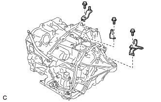
Remove the 3 bolts and 3 wire harness clamp brackets from the transaxle case sub-assembly.
-
-
REMOVE TRANSMISSION CASE PLUG ASSEMBLY
-
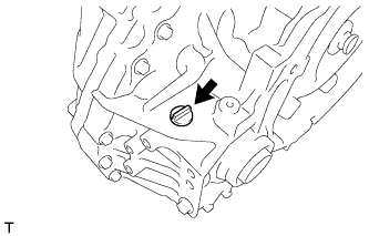
Remove the transmission case plug assembly from the transaxle housing.
-
Remove the O-ring from the transmission case plug assembly.
-
-
REMOVE TORQUE CONVERTER ASSEMBLY
-
Remove the torque converter assembly from the automatic transaxle assembly.
-