FRONT DRIVE SHAFT ASSEMBLY (for 2GR-FE) INSTALLATION
-
INSTALL FRONT DRIVE SHAFT ASSEMBLY LH
-
Coat the spline of the front drive inboard joint assembly with ATF WS.
-
Coat the lip of the transaxle case oil seal with MP grease.
-
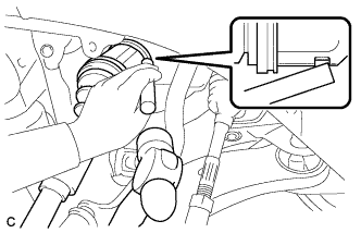
Align the inboard joint splines, and using a brass bar and a hammer, install the front drive shaft assembly LH.
Note
-
Face the end gap of the front drive shaft hole snap ring LH downward.
-
Do not damage the transaxle case oil seal.
-
Do not damage the front axle inboard joint boot.
-
Make sure to center the front drive shaft assembly LH during installation to prevent damage to the front drive shaft hole snap ring LH.
Tech Tips
Confirm whether the drive shaft is securely driven in by checking the reaction force and sound.
-
-
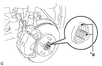
Text in Illustration *a Matchmark Align the matchmarks and install the front drive shaft assembly LH to the front axle hub sub-assembly.
Note
Be careful not to damage the front axle outboard joint boot or speed sensor rotor.
-
-
INSTALL FRONT DRIVE SHAFT ASSEMBLY RH
-
Coat the spline of the front drive inboard joint assembly with ATF WS.
-
Coat the lip of the front transaxle case oil seal with MP grease.
-
Install a new bearing bracket hole snap ring to the front drive shaft assembly RH.
-
Install the front drive shaft assembly RH.
Note
-
Do not damage the front transaxle case oil seal.
-
Do not damage the front axle inboard joint boot.
-
When inserting the front drive shaft assembly RH, keep it level.
-
-
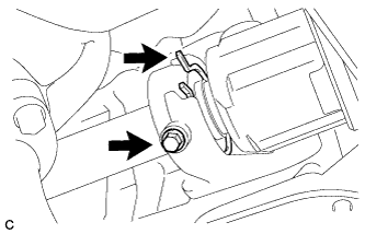
Install the bearing bracket hole snap ring and a new bolt.
- Torque:
- 32 N*m { 330 kgf*cm, 24 ft.*lbf }
-
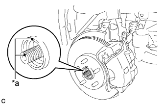
Text in Illustration *a Matchmark Align the matchmarks and install the front drive shaft assembly RH to the front axle hub sub-assembly.
Note
Be careful not to damage the front axle outboard joint boot or speed sensor rotor.
-
-
CONNECT FRONT LOWER NO. 1 SUSPENSION ARM SUB-ASSEMBLY
-
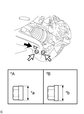
Text in Illustration *A for TMC, TMMR Made *B for TMMK Made *a 20 mm (0.787 in.) *b 22 mm (0.866 in.) 
Bolt 
Nut Connect the front lower No. 1 suspension arm sub-assembly to the front lower ball joint assembly with the bolt and 2 nuts.
- Torque:
- for TMC, TMMR Made
- 75 N*m { 765 kgf*cm, 55 ft.*lbf }
- for TMMK Made
- 92 N*m { 938 kgf*cm, 68 ft.*lbf }
Note
-
The tightening torque for the bolt differs depending on the type of nut.
-
Make sure to tighten the bolt to the same torque as the nuts.
-
-
CONNECT TIE ROD ASSEMBLY
-
Connect the tie rod assembly LH to the steering knuckle with the nut.
- Torque:
- 49 N*m { 500 kgf*cm, 36 ft.*lbf }
-
Install a new cotter pin.
Note
Further tighten the nut up to 60° if the holes for the cotter pin are not aligned.
-
-
INSTALL FRONT SPEED SENSOR
-
Install the front speed sensor and front flexible hose to the front shock absorber assembly with the bolt and clamp.
- Torque:
- 19 N*m { 192 kgf*cm, 14 ft.*lbf }
Note
Do not twist the front speed sensor when installing it.
Tech Tips
Install the speed sensor harness bracket first and then the front flexible hose.
-
Install the front speed sensor to the steering knuckle with the bolt.
- Torque:
- 8.5 N*m { 87 kgf*cm, 75 in.*lbf }
Note
Do not twist the front speed sensor when installing it.
-
-
INSTALL FRONT STABILIZER LINK ASSEMBLY
-
for Steel Type:
-
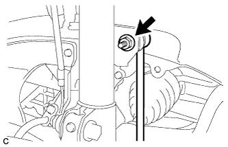
Install the front stabilizer link assembly to the front shock absorber assembly with the nut.
- Torque:
- 74 N*m { 755 kgf*cm, 55 ft.*lbf }
If the ball joint turns together with the nut, use a hexagon wrench to hold the stud bolt.
-
-
for Aluminum Type:
-
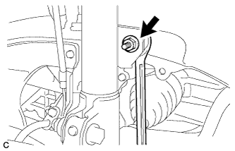
Install the front stabilizer link assembly to the front shock absorber assembly with the nut.
- Torque:
- for TMC, TMMR Made
- 74 N*m { 755 kgf*cm, 55 ft.*lbf }
- for TMMK Made
- 125 N*m { 1275 kgf*cm, 92 ft.*lbf }
If the ball joint turns together with the nut, use a wrench to hold the stud bolt.
-
-
-
INSTALL FRONT AXLE SHAFT NUT
-
Clean the threaded parts on the front drive shaft assembly and a new axle shaft nut using a non-residue solvent.
Note
-
Be sure to perform this work even when using a new drive shaft.
-
Keep the threaded parts free of oil and foreign matter.
-
-
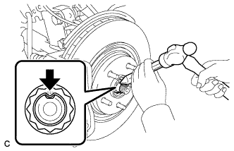
Using a socket wrench (30 mm), install the front axle shaft nut.
- Torque:
- 294 N*m { 2998 kgf*cm, 217 ft.*lbf }
-
Using a chisel and a hammer, stake the front axle shaft nut.
-
-
INSTALL FRONT WHEELS
- Torque:
- 103 N*m { 1049 kgf*cm, 76 ft.*lbf }
-
ADD AUTOMATIC TRANSAXLE FLUID
-
INSTALL FRONT FENDER APRON SEAL LH
-
INSTALL FRONT FENDER APRON SEAL RH
-
INSTALL ENGINE UNDER COVER LH
-
INSTALL FRONT WHEEL OPENING EXTENSION PAD LH
-
INSTALL ENGINE UNDER COVER RH
-
INSTALL FRONT WHEEL OPENING EXTENSION PAD RH
-
ADJUST FRONT WHEEL ALIGNMENT
-
CHECK FOR SPEED SENSOR SIGNAL