VALVE BODY ASSEMBLY INSTALLATION
-
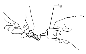
INSTALL MANUAL VALVE
-
Coat the manual valve with ATF.
-
Install the manual valve to the transmission valve body assembly.
-
-
INSTALL TRANSAXLE CASE GASKET
-
Coat 2 new transaxle case gaskets with ATF.
-
Install the 2 transaxle case gaskets to the transaxle case sub-assembly.
-
-
INSTALL TRANSMISSION VALVE BODY ASSEMBLY
-
Coat the O-ring of the transmission wire with ATF.
-
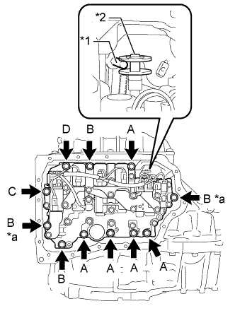
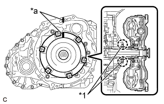
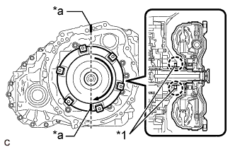
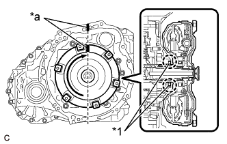
Text in Illustration *1 Manual Valve Lever Shaft Sub-assembly Pin *2 Manual Valve *a Positioning Bolt Insert the manual valve lever shaft sub-assembly pin into the groove on the end of the manual valve as shown in the illustration and temporarily install the transmission valve body assembly to the transaxle case sub-assembly with the 11 bolts.
Bolt Length Bolt Length (mm (in.)) (A) 25 (0.984) (B) 30 (1.18) (C) and (D) 35 (1.38) Note
-
When installing the transmission valve body assembly, be careful not to allow the transmission revolution sensor and transaxle case sub-assembly to interfere with each other.
-
Be sure to insert the manual valve lever shaft sub-assembly pin into the groove on the end of the manual valve.
-
-
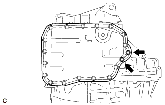
Fully tighten the 2 positioning bolts shown in the illustration.
- Torque:
- 10.8 N*m { 110 kgf*cm, 8 ft.*lbf }
-
Fully tighten the 9 bolts to install the transmission valve body assembly.
- Torque:
- Bolt (A), (B), (C)
- 10.8 N*m { 110 kgf*cm, 8 ft.*lbf }
- Bolt (D)
- 9.6 N*m { 98 kgf*cm, 85 in.*lbf }
-
-
INSTALL VALVE BODY OIL STRAINER ASSEMBLY
-
Coat a new O-ring with ATF.
-
Install the O-ring to the valve body oil strainer assembly.
Note
Ensure that the O-ring is not twisted.
-
Install the valve body oil strainer assembly to the transmission valve body assembly with the 2 bolts.
- Torque:
- 9.6 N*m { 98 kgf*cm, 85 in.*lbf }
-
-
INSTALL TRANSMISSION OIL CLEANER MAGNET
-
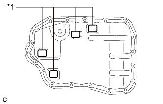
Text in Illustration *1 Transmission Oil Cleaner Magnet Install the 4 transmission oil cleaner magnets to the automatic transaxle oil pan sub-assembly as shown in the illustration.
-
-
INSTALL AUTOMATIC TRANSAXLE OIL PAN GASKET
-
Install a new automatic transaxle oil pan gasket to the automatic transaxle oil pan sub-assembly.
-
-
INSTALL AUTOMATIC TRANSAXLE OIL PAN SUB-ASSEMBLY
-
Clean and degrease the 2 bolts and installation holes in the transaxle case sub-assembly.
-
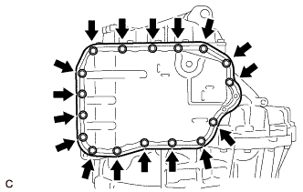
Install the automatic transaxle oil pan sub-assembly with automatic transaxle oil pan gasket to the transaxle case sub-assembly with the 17 bolts.
- Torque:
- 7.5 N*m { 76 kgf*cm, 66 in.*lbf }
Note
Completely remove any oil or grease from the contact surfaces of the transaxle case sub-assembly and automatic transaxle oil pan sub-assembly with automatic transaxle oil pan gasket before installation.
-
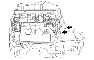
Text in Illustration *a Adhesive Apply adhesive to 2 or 3 threads on the ends of the 2 bolts.
Adhesive Toyota Genuine Adhesive 1344, Three Bond 1344 or equivalent Note
In order to ensure proper sealing of the 2 bolts, apply adhesive to the 2 bolts and install them within 10 minutes of adhesive application.
-
Install the 2 bolts.
- Torque:
- 7.0 N*m { 71 kgf*cm, 62 in.*lbf }
-
-
INSTALL TORQUE CONVERTER ASSEMBLY
-
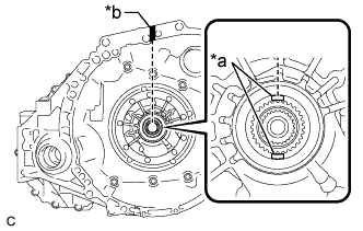
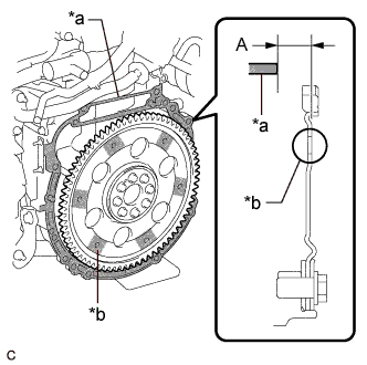
Text in Illustration *a Key *b Matchmark Turn the front oil pump drive gear so that the key is at the top and place a matchmark on the transaxle housing to indicate the position of the key.
-
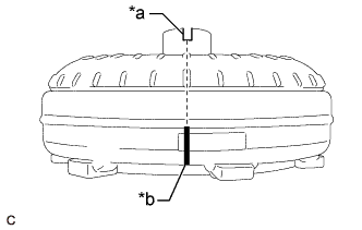
Text in Illustration *a Groove *b Matchmark Place a matchmark on the torque converter assembly so that the position of its groove is clearly indicated.
-
Text in Illustration *1 Front Oil Pump Oil Seal *a Matchmark Align the matchmark on the transaxle housing with the one on the torque converter assembly and engage the splines of the input shaft with the turbine runner splines.
Note
-
Install the torque converter assembly to the input shaft while keeping it horizontal.
-
Do not damage the front oil pump oil seal.
-
-
Text in Illustration *1 Front Oil Pump Oil Seal *a Matchmark Rotate the torque converter assembly approximately 180° and engage the splines of the stator shaft with the stator assembly.
Note
-
Do not push the torque converter assembly excessively when rotating it.
-
Install the torque converter assembly to the input shaft while keeping it horizontal.
-
Do not damage the front oil pump oil seal.
-
-
Text in Illustration *1 Front Oil Pump Oil Seal *a Matchmark Rotate the torque converter assembly approximately 180° again, align the matchmark on the torque converter assembly with the one on the transaxle housing and insert the groove of the torque converter assembly into the key of the front oil pump drive gear.
Note
-
Do not push the torque converter assembly excessively when rotating it.
-
Install the torque converter assembly to the input shaft while keeping it horizontal.
-
Do not damage the front oil pump oil seal.
-
-
Clean the drive plate and torque converter assembly setting bolt holes.
-
Text in Illustration *a Engine Assembly Surface *b Drive Plate and Ring Gear Sub-assembly Surface Using a vernier caliper and straightedge, measure the dimension (A) between the automatic transaxle assembly contact surface of the engine assembly*a and the torque converter assembly contact surface of the drive plate and ring gear sub-assembly*b.
Note
Make sure to deduct the thickness of the straightedge.
-
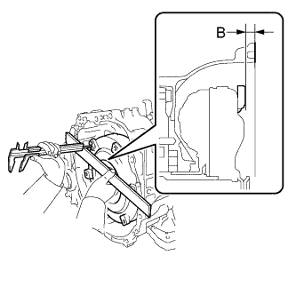
Using a vernier caliper and straightedge, measure the dimension (B) shown in the illustration and check that the dimension (B) is more than the dimension (A), which was measured in the previous step.
Standard Dimension (A) + 1 mm (0.0394 in.) or more Note
-
Make sure to deduct the thickness of the straightedge.
-
If the automatic transaxle assembly is installed to the engine assembly with the torque converter assembly not sufficiently inserted, the torque converter assembly may be damaged.
-
Do not include the thickness of the set block.
-
-
-
INSTALL AUTOMATIC TRANSAXLE ASSEMBLY
-
CHECK AUTOMATIC TRANSAXLE SYSTEM