AUTOMATIC TRANSAXLE SYSTEM, Diagnostic DTC:P271313
| DTC Code | DTC Name |
|---|---|
| P271313 | Pressure Control Solenoid "D" Circuit Open |
DESCRIPTION
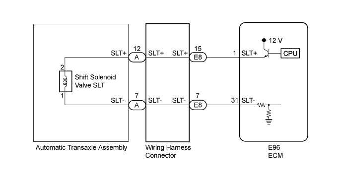
The shift solenoid valve SLT controls the transmission line pressure for smooth transmission operation based on signals from the throttle position sensor and vehicle speed sensor. The ECM adjusts the current to the shift solenoid valve SLT to control hydraulic line pressure coming from the primary regulator valve. Appropriate line pressure assures smooth shifting with varying engine outputs.
| DTC No. | DTC Detection Condition | Trouble Area |
|---|---|---|
| P271313 | 1. Diagnosis Condition 2. Malfunction Status 3. Malfunction Time 4. Other
|
|
MONITOR DESCRIPTION
When an open or short in the linear solenoid valve SLT circuit is detected, the ECM interprets this as a malfunction, illuminates the MIL and stores this DTC.
WIRING DIAGRAM
INSPECTION PROCEDURE
Note
Perform registration and/or initialization when parts related to the automatic transaxle are replaced Click here.
Tech Tips
After inspection repair, clear the DTCs and perform the following procedure to check that DTCs are not output.
-
Start the engine.
-
Check for DTCs again Click here.
PROCEDURE
-
CHECK HARNESS AND CONNECTOR (SHIFT SOLENOID VALVE SLT CIRCUIT)
-
Disconnect the E96 ECM connector.
-
Measure the resistance according to the value(s) in the table below.
Standard Resistance Tester Connection Condition Specified Condition E96-1 (SLT+) - E96-31 (SLT-) 20°C (68°F) 5.0 to 5.6 Ω E96-1 (SLT+) - Body ground and other terminals Always 10 kΩ or higher E96-31 (SLT-) - Body ground and other terminals Always 10 kΩ or higher
NG 
CHECK HARNESS AND CONNECTOR (ECM - WIRING HARNESS CONNECTOR) Click here
OK 
REPLACE ECM Click here
-
-
CHECK HARNESS AND CONNECTOR (ECM - WIRING HARNESS CONNECTOR)
-
Disconnect the E8 connector from the wiring harness connector.
-
Measure the resistance according to the value(s) in the table below.
Standard Resistance Tester Connection Condition Specified Condition E96-1 (SLT+) - E8-15 (SLT+) Always Below 1 Ω E96-31 (SLT-) - E8-7 (SLT-) Always Below 1 Ω E96-1 (SLT+) or E8-15 (SLT+) - Body ground and other terminals Always 10 kΩ or higher E96-31 (SLT-) or E8-7 (SLT-) - Body ground and other terminals Always 10 kΩ or higher
NG 
REPAIR OR REPLACE HARNESS OR CONNECTOR
OK 
-
-
INSPECT TRANSMISSION WIRE (SLT)
-
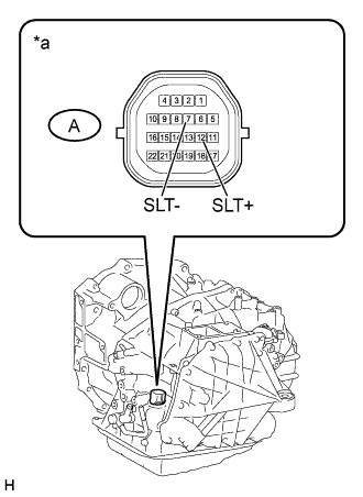
Text in Illustration *a Component without harness connected
(Transmission Wire)
Remove the wiring harness connector.
-
Measure the resistance according to the value(s) in the table below.
Standard Resistance Tester Connection Condition Specified Condition A-12 (SLT+) - A-7 (SLT-) 20°C (68°F) 5.0 to 5.6 Ω A-12 (SLT+) - Body ground and other terminals Always 10 kΩ or higher A-7 (SLT-) - Body ground and other terminals Always 10 kΩ or higher
NG
INSPECT SHIFT SOLENOID VALVE SLT Click here
OK
REPLACE WIRING HARNESS CONNECTOR Click here
-
-
INSPECT SHIFT SOLENOID VALVE SLT
-
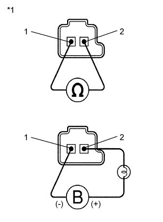
Text in Illustration *1 Shift Solenoid Valve SLT Remove the shift solenoid valve SLT.
-
Measure the resistance according to the value(s) in the table below.
Standard Resistance Tester Connection Condition Specified Condition 1 - 2 20°C (68°F) 5.0 to 5.6 Ω -
Connect a positive (+) lead from the battery with a 21 W bulb to terminal 2 and a negative (-) lead to terminal 1 of the solenoid valve connector. Check that the valve moves and makes an operating sound.
OK Valve moves and makes an operating sound.
NG
REPLACE SHIFT SOLENOID VALVE SLT Click here
OK
REPLACE TRANSMISSION WIRE Click here
-