PARK / NEUTRAL POSITION SWITCH INSTALLATION
-
INSTALL PARK/NEUTRAL POSITION SWITCH ASSEMBLY
-
Temporarily install the park/neutral position switch assembly to the transaxle case sub-assembly with the 2 bolts.
Note
Before installing the park/neutral position switch assembly, remove any dirt or rust on the manual valve lever shaft sub-assembly. Be sure to install the park/neutral position switch assembly straight along the manual valve lever shaft sub-assembly while being careful not to deform the plate spring that supports the manual valve lever shaft sub-assembly. If the plate spring is deformed, the park/neutral position switch assembly cannot be installed correctly.
-
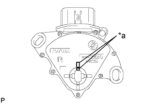
Text in Illustration *a Protrusion Align the protrusions of the park/neutral position switch assembly as shown in the illustration.
-
Hold the park/neutral position switch assembly in position and tighten the 2 bolts.
- Torque:
- 5.4 N*m { 55 kgf*cm, 48 in.*lbf }
Note
After installing the park/neutral position switch assembly, confirm that the 2 protrusions on the park/neutral position switch assembly are aligned.
-
Connect the park/neutral position switch assembly connector.
-
-
INSTALL TRANSMISSION CONTROL SHAFT LEVER
-
Install the transmission control shaft lever to the manual valve lever shaft sub-assembly with the washer and nut.
- Torque:
- 12.7 N*m { 130 kgf*cm, 9 ft.*lbf }
-
-
CONNECT TRANSMISSION CONTROL CABLE ASSEMBLY
-
Move the shift lever to N.
-
Connect the transmission control cable assembly to the transmission control shaft lever with the nut.
- Torque:
- 13 N*m { 133 kgf*cm, 10 ft.*lbf }
-
Install the transmission control cable assembly to the No. 1 transmission control cable bracket with a new clip.
-
-
CONNECT ENGINE WIRE
-
Engage the clamp to connect the engine wire to the automatic transaxle assembly.
-
Install the nut to the wire harness clamp bracket.
- Torque:
- 8.0 N*m { 82 kgf*cm, 71 in.*lbf }
-
-
INSTALL AIR CLEANER CASE SUB-ASSEMBLY
-
INSTALL AIR CLEANER FILTER ELEMENT SUB-ASSEMBLY
-
INSTALL AIR CLEANER CAP WITH AIR CLEANER HOSE
-
Connect the air cleaner cap with air cleaner hose to the throttle body with motor assembly.
-
Install the air cleaner cap with air cleaner hose with the 2 guides and 2 air cleaner cap clamps.
-
Tighten the hose clamp.
-
Connect the union to connector tube hose to the air cleaner hose sub-assembly.
-
Engage the wire harness clamp.
-
Connect the mass air flow meter sub-assembly connector.
-
Engage the ventilation hose clamp.
-
Connect the ventilation hose to the cylinder head cover sub-assembly and slide the clip to secure it.
-
-
INSTALL INLET AIR CLEANER ASSEMBLY
-
INSTALL COOL AIR INTAKE DUCT SEAL
-
INSPECT PARK/NEUTRAL POSITION SWITCH ASSEMBLY OPERATION
-
Apply the parking brake.
-
Turn the engine switch on (IG).
-
Depress the brake pedal and check that the engine starts when the shift lever is in N or P, but does not start in any other position.
-
Check that the back-up lights come on when the shift lever is moved to R, but do not come on in any other position. If the operation is not as specified, check the park/neutral position switch assembly for continuity.
-
-
INSTALL NO. 1 ENGINE COVER SUB-ASSEMBLY
-
INSPECT SHIFT LEVER POSITION
-
When the shift lever is moved from P to R with the engine switch ON and brake pedal depressed, make sure that the shift lever moves smoothly and correctly to P.
-
Start the engine and check that the vehicle moves forward when the shift lever is moved from N to D and moves rearward when the shift lever is moved to R.
-
-
ADJUST SHIFT LEVER POSITION
-
Move the shift lever to N.
-
Remove the console box assembly Click here.
-
Disconnect the end of the transmission control cable assembly from the lower shift lever assembly.
-
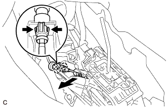
Disengage the 2 claws and disconnect the transmission control cable assembly from the lower shift lever assembly.
-
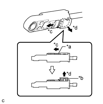
Text in Illustration *a Slider *b Lock Piece *c Slide *d Pull Slide the slider of the transmission control cable assembly as shown in the illustration and pull the lock piece outward.
-
Engage the 2 claws to connect the transmission control cable assembly to the lower shift lever assembly.
-
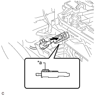
Text in Illustration *a Lock Piece Connect the end of the transmission control cable assembly to the lower shift lever assembly.
Note
-
Check that the lock piece is pulled out.
-
Push the end of the transmission control cable assembly all the way to the base of the lower shift lever assembly pin.
-
-
Push the lock piece into the adjuster case.
Note
-
Check that the park/neutral position switch assembly and the shift lever are in neutral.
-
Securely push in the lock piece until the slider lock is engaged.
-
-
After adjusting the shift lever position, check the operation and function of the shift lever. If there is a problem, adjust the position again.
-
Install the console box assembly Click here.
-