SHIFT LEVER (for TMC, TMMR Made) INSPECTION
-
INSPECT LOWER SHIFT LEVER ASSEMBLY (w/o Smart Entry and Start System)
-
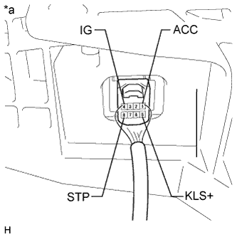
Text in Illustration *a Component with harness connected
(Shift Lock Control ECU)
Measure the voltage according to the value(s) in the table below.
Standard Voltage Tester Connection Condition Specified Condition 1 (ACC) - Body ground Ignition switch ON 11 to 14 V Ignition switch ACC 11 to 14 V Ignition switch off Below 1 V 8 (STP) - Body ground Brake pedal depressed 11 to 14 V Brake pedal released Below 1 V 5 (KLS+) - Body ground Ignition switch ACC and shift lever in P Below 1 V Ignition switch ACC and shift lever except in P (Within approx. 1 second) 7.5 to 11 V Ignition switch ACC and shift lever in P (After approx. 1 second) 6.0 to 9.5 V 4 (IG) - Body ground Ignition switch ON 11 to 14 V Ignition switch off Below 1 V Tech Tips
Do not disconnect the lower shift lever assembly connector.
-
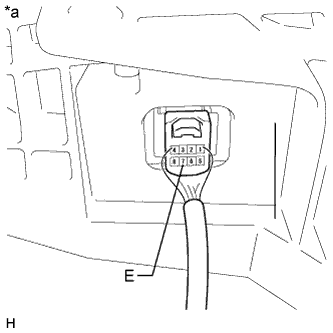
Text in Illustration *a Component with harness connected
(Shift Lock Control ECU)
Measure the resistance according to the value(s) in the table below.
Standard Resistance Tester Connection Condition Specified Value 7 (E) - Body ground Always Below 1 Ω Tech Tips
Do not disconnect the lower shift lever assembly connector.
-
Inspect shift lock solenoid
-
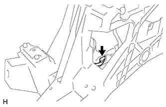
Disconnect the shift lock solenoid connector.
-
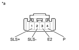
Text in Illustration *a Front view of wire harness connector
(to Shift Lock Solenoid)
Measure the resistance according to the value(s) in the table below when the shift lever is moved to each position.
Standard Resistance Tester Connection Shift Lever Position Specified Condition 4 (P) - 3 (E2) P 10 kΩ or higher Other than P Below 1 Ω
-
If the result is not as specified, replace the lower shift lever assembly.
-
If the shift lock does not operate when the power source of the lower shift lever assembly is normal and the resistance between the body ground and the shift lock solenoid is as specified, replace the lower shift lever assembly.
-
-
Measure the resistance according to the value(s) in the table below.
Standard Resistance Tester Connection Condition Specified Condition 1 (SLS+) - 2 (SLS-) Always 112 Ω
-
If the result is not as specified, replace the lower shift lever assembly.
-
If the shift lock does not operate when the power source of the lower shift lever assembly is normal and the resistance between the body ground and the shift lock solenoid is as specified, replace the lower shift lever assembly.
-
-
-
-
INSPECT LOWER SHIFT LEVER ASSEMBLY (w/ Smart Entry and Start System)
-
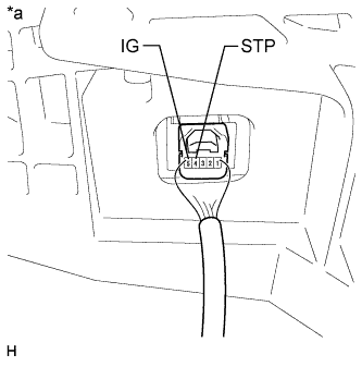
Text in Illustration *a Component with harness connected
(Shift Lock Control ECU)
Measure the voltage according to the value(s) in the table below.
Standard Voltage Tester Connection Condition Specified Condition 5 (IG) - Body ground Engine switch on (IG) 11 to 14 V Engine switch off Below 1 V 4 (STP) - Body ground Brake pedal depressed 11 to 14 V Brake pedal released Below 1 V Tech Tips
Do not disconnect the lower shift lever assembly connector.
-
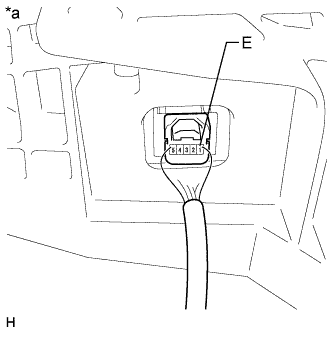
Text in Illustration *a Component with harness connected
(Shift Lock Control ECU)
Measure the resistance according to the value(s) in the table below.
Standard Resistance Tester Connection Condition Specified Condition 1 (E) - Body ground Always Below 1 Ω Tech Tips
Do not disconnect the lower shift lever assembly connector.
-
Inspect shift lock solenoid
-
Disconnect the shift lock solenoid connector.
-
Text in Illustration *a Front view of wire harness connector
(to Shift Lock Solenoid)
Measure the resistance according to the value(s) in the table below when the shift lever is moved to each position.
Standard Resistance Tester Connection Shift Lever Position Specified Condition 4 (P) - 3 (E2) P 10 kΩ or higher Other than P Below 1 Ω
-
If the result is not as specified, replace the lower shift lever assembly.
-
If the shift lock does not operate when the power source of the lower shift lever assembly is normal and the resistance between the body ground and the shift lock solenoid is as specified, replace the lower shift lever assembly.
-
-
Measure the resistance according to the value(s) in the table below.
Standard Resistance Tester Connection Condition Specified Condition 1 (SLS+) - 2 (SLS-) Always 112 Ω
-
If the result is not as specified, replace the lower shift lever assembly.
-
If the shift lock does not operate when the power source of the lower shift lever assembly is normal and the resistance between the body ground and the shift lock solenoid is as specified, replace the lower shift lever assembly.
-
-
-
-
INSPECT TRANSMISSION CONTROL SWITCH (for LHD)
-
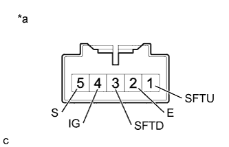
Text in Illustration *a Component without harness connected
(Transmission Control Switch)
Measure the resistance between each terminal of the shift lock control unit assembly when the shift lever is moved to each position.
Standard Resistance Tester Connection Condition Specified Condition 4 (IG) - 5 (S) Shift lever in S, "+" or "-" Below 1 Ω Shift lever not in S, "+" or "-" 10 kΩ or higher 3 (SFTU) - 2 (E) Shift lever held in "+"
(Up-shift)
Below 1 Ω Shift lever not held in "+" 10 kΩ or higher 1 (SFTD) - 2 (E) Shift lever held in "-"
(Down-shift)
Below 1 Ω Shift lever not held in "-" 10 kΩ or higher If the resistance value is not as specified, replace the lower shift lever assembly.
-
-
INSPECT TRANSMISSION CONTROL SWITCH (for RHD)
-
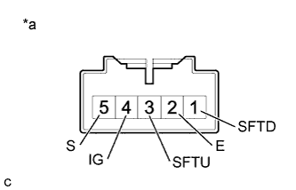
Text in Illustration *a Component without harness connected
(Transmission Control Switch)
Measure the resistance between each terminal of the shift lock control unit assembly when the shift lever is moved to each position.
Standard Resistance Tester Connection Condition Specified Condition 4 (IG) - 5 (S) Shift lever in S, "+" or "-" Below 1 Ω Shift lever not in S, "+" or "-" 10 kΩ or higher 1 (SFTU) - 2 (E) Shift lever held in "+"
(Up-shift)
Below 1 Ω Shift lever not held in "+" 10 kΩ or higher 3 (SFTD) - 2 (E) Shift lever held in "-"
(Down-shift)
Below 1 Ω Shift lever not held in "-" 10 kΩ or higher If the resistance value is not as specified, replace the lower shift lever assembly.
-