AUTOMATIC TRANSAXLE SYSTEM Transmission Control Switch Circuit
DESCRIPTION
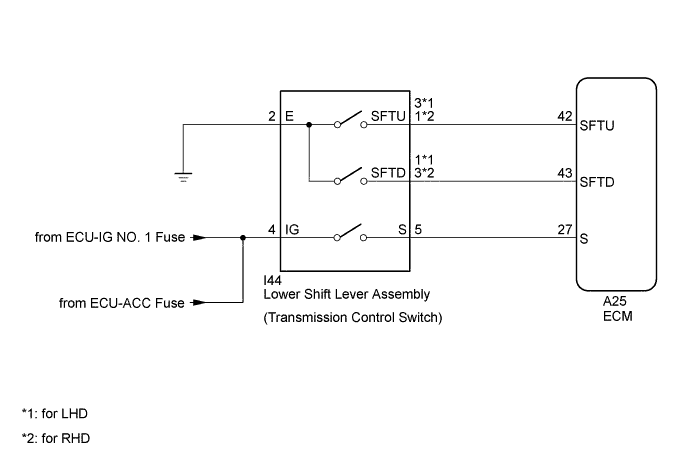
When the shift lever is in S and it is moved toward "-" or "+", it is possible to select different shift ranges (1st through 6th ranges).
Moving the shift lever toward "+" increases the shift range by one, and moving the shift lever toward "-" decreases the shift range by one.
WIRING DIAGRAM
INSPECTION PROCEDURE
Note
Inspect the fuses for circuits related to this system before performing the following inspection procedure.
PROCEDURE
-
READ VALUE USING INTELLIGENT TESTER (SPORT SHIFT SWITCH STATUS)
-
Connect the intelligent tester to the DLC3.
-
Turn the ignition switch to ON.
-
Turn the intelligent tester on.
-
Enter the following menus: Powertrain / Engine and ECT / Data List.
-
In accordance with the display on the intelligent tester, read the Data List.
Tester Display Measurement Item/Range Normal Condition Diagnostic Note Sports Shift Up SW Sport shift up switch status/
ON or OFF
-
ON: Continuously shift to "+" (up-shift)
-
OFF: Release "+" (up-shift)
- Sports Shift Down SW Sport shift down switch status/
ON or OFF
-
ON: Continuously shift to "-" (down-shift)
-
OFF: Release "-" (down-shift)
- Result Result Proceed to Data display is not within Normal Condition range A Data display is within Normal Condition range B -
B 
CHECK FOR INTERMITTENT PROBLEMS Click here
A 
-
-
CHECK HARNESS AND CONNECTOR (BATTERY - TRANSMISSION CONTROL SWITCH)
-
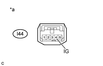
Text in Illustration *a Front view of wire harness connector
(to Transmission Control Switch)
Disconnect the transmission control switch connector from lower shift lever assembly.
-
Measure the voltage according to the value(s) in the table below.
Standard Voltage Tester Condition Condition Specified Condition l44-4 (IG) - Body ground Ignition switch ON 11 to 14 V Ignition switch off Below 1 V
NG
CHECK POWER SOURCE CIRCUIT
OK
-
-
CHECK HARNESS AND CONNECTOR (TRANSMISSION CONTROL SWITCH - BODY GROUND)
-
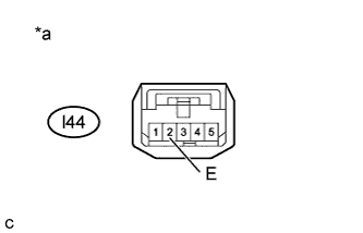
Text in Illustration *a Front view of wire harness connector
(to Transmission Control Switch)
Measure the resistance according to the value(s) in the table below.
Standard Resistance Tester Connection Condition Specified Condition l44-2 (E) - Body ground Always Below 1 Ω
NG
REPAIR OR REPLACE HARNESS OR CONNECTOR
OK
-
-
INSPECT LOWER SHIFT LEVER ASSEMBLY (TRANSMISSION CONTROL SWITCH)
-

Measure the resistance between each terminal of the transmission control switch when the shift lever is moved to each position.
Standard Resistance (for LHD) Tester Connection Condition Specified Condition l44-4 (IG) - l44-5 (S) Shift lever in S, "+" or "-" Below 1 Ω Shift lever not in S, "+" or "-" 10 kΩ or higher l44-3 (SFTU) - l44-2 (E) Shift lever held in "+"
(Up-shift)
Below 1 Ω Shift lever not held in "+" 10 kΩ or higher l44-1 (SFTD) - l44-2 (E) Shift lever held in "-"
(Down-shift)
Below 1 Ω Shift lever not held in "-" 10 kΩ or higher Standard Resistance (for RHD) Tester Connection Condition Specified Condition l44-4 (IG) - l44-5 (S) Shift lever in S, "+" or "-" Below 1 Ω Shift lever not in S, "+" or "-" 10 kΩ or higher l44-1 (SFTU) - l44-2 (E) Shift lever held in "+"
(Up-shift)
Below 1 Ω Shift lever not held in "+" 10 kΩ or higher l44-3 (SFTD) - l44-2 (E) Shift lever held in "-"
(Down-shift)
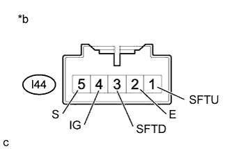
Below 1 Ω Shift lever not held in "-" 10 kΩ or higher Text in Illustration *a Component without harness connected
(Transmission Control Switch for LHD)
*b Component without harness connected
(Transmission Control Switch for RHD)
Result Result Proceed to OK A NG (for TMC, TMMR Made) B NG (for TMMK Made) C
B
REPLACE LOWER SHIFT LEVER ASSEMBLY (TRANSMISSION CONTROL SWITCH) Click here
C
REPLACE LOWER SHIFT LEVER ASSEMBLY (TRANSMISSION CONTROL SWITCH) Click here
A
-
-
CHECK HARNESS AND CONNECTOR (TRANSMISSION CONTROL SWITCH - ECM)
-
Connect the transmission control switch connector.
-
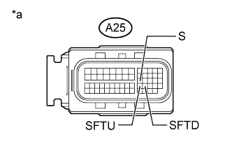
Text in Illustration *a Front view of wire harness connector
(to ECM)
Disconnect the ECM connector.
-
Turn the ignition switch to ON.
-
Measure the voltage according to the value(s) in the table below.
Standard Voltage Tester Connection Condition Specified Condition A25-27 (S) - Body ground
-
Ignition switch ON
-
Shift lever in S, "+" or "-"
11 to 14 V A25-27 (S) - Body ground
-
Ignition switch ON
-
Shift lever not in S, "+" or "-"
Below 1 V -
-
Turn the ignition switch off.
-
Measure the resistance according to the value(s) in the table below.
Standard Resistance Tester Connection Condition Specified Condition A25-42 (SFTU) - Body ground Shift lever held in "+"
(Up-shift)
Below 1 Ω Shift lever not held in "+" 10 kΩ or higher A25-43 (SFTD) - Body ground Shift lever held in "-"
(Down-shift)
Below 1 Ω Shift lever not held in "-" 10 kΩ or higher
NG
REPAIR OR REPLACE HARNESS OR CONNECTOR
OK 
REPLACE ECM Click here
-