DIFFERENTIAL CASE REASSEMBLY

-
INSTALL FRONT DIFFERENTIAL CASE REAR TAPERED ROLLER BEARING
-
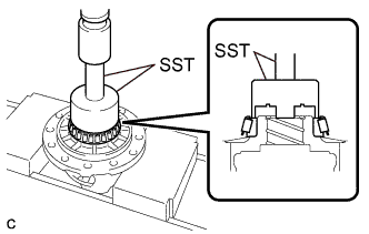
Using SST and a press, install a new front differential case rear tapered roller bearing (inner race) to the front differential case.
- SST
- 09726-36010
- 09950-70010 ( 09951-07100 )
Note
-
Do not damage the front differential case rear tapered roller bearing (inner race) cage when installing the front differential case rear tapered roller bearing (inner race).
-
Ensure that there is no clearance between the front differential case rear tapered roller bearing (inner race) and front differential case.
-
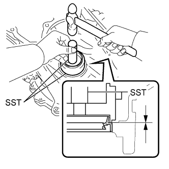
Using SST and a hammer, install a new front differential case rear tapered roller bearing (outer race) to the transaxle case sub-assembly.
- SST
- 09950-60020 ( 09951-00890 )
- 09950-70010 ( 09951-07150 )
Note
Ensure that there is no clearance between the front differential case rear tapered roller bearing (outer race) and transaxle case sub-assembly.
-
-
INSTALL FRONT DIFFERENTIAL CASE FRONT TAPERED ROLLER BEARING
-
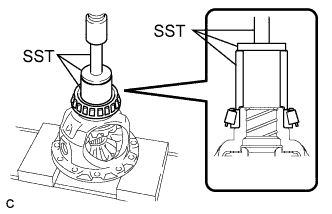
Using SST and a press, install a new front differential case front tapered roller bearing (inner race) to the front differential case.
- SST
- 09710-30012 ( 09710-04081 )
- 09950-60010 ( 09951-00480 )
- 09950-70010 ( 09951-07100 )
Note
-
Do not damage the front differential case front tapered roller bearing (inner race) cage when installing the front differential case front tapered roller bearing (inner race).
-
Ensure that there is no clearance between the front differential case front tapered roller bearing (inner race) and front differential case.
-
Install the shim to the transaxle housing.
-
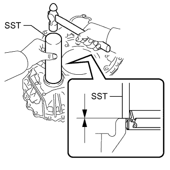
Using SST and a hammer, install a new front differential case front tapered roller bearing (outer race) to the transaxle housing.
- SST
- 09950-60020 ( 09951-00890 )
- 09950-70010 ( 09951-07150 )
Note
Ensure that there is no clearance between the front differential case front tapered roller bearing (outer race), shim and transaxle housing.
-
-
INSTALL FRONT DIFFERENTIAL SIDE GEAR
-
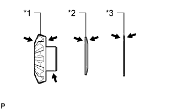
Text in Illustration *1 Front Differential Side Gear *2 Conical Spring *3 Front No. 1 Differential Side Gear Thrust Washer 
ATF Coat the 2 front differential side gears, 2 front No. 1 differential side gear thrust washers and 2 conical springs with ATF.
-
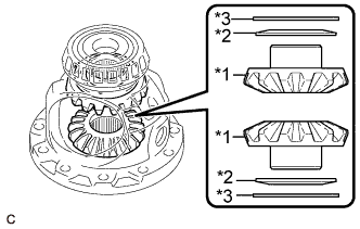
Text in Illustration *1 Front Differential Side Gear *2 Conical Spring *3 Front No. 1 Differential Side Gear Thrust Washer Install the 2 front differential side gears, 2 front No. 1 differential side gear thrust washers and 2 conical springs to the front differential case.
Note
-
Do not drop the front differential side gear, front No. 1 differential side gear thrust washer or conical spring.
-
Make sure that the conical spring is installed with the correct orientation.
-
-
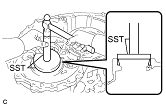
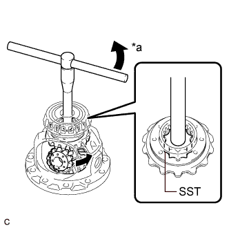
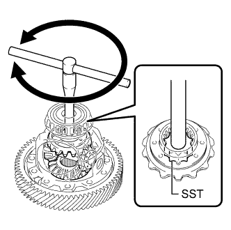
Install SST as shown in the illustration and tighten it.
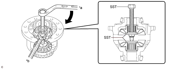
Text in Illustration *a Turn *b Hold - SST
- 09528-52010 ( 09528-05010, 09953-05010 )
Note
Do not overtighten SST as doing so will damage the front differential side gears, conical springs, front No. 1 differential side gear thrust washers and front differential case.
Tech Tips
-
Tighten SST to create the necessary clearance to install the front differential pinions.
-
When installing the front differential pinions, do not overtighten SST, as it is necessary to rotate the front differential side gears.
-
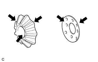
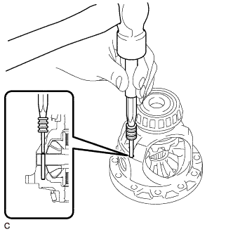
Coat the 2 front differential pinions and 2 front differential pinion thrust washers with ATF.
Text in Illustration ATF -
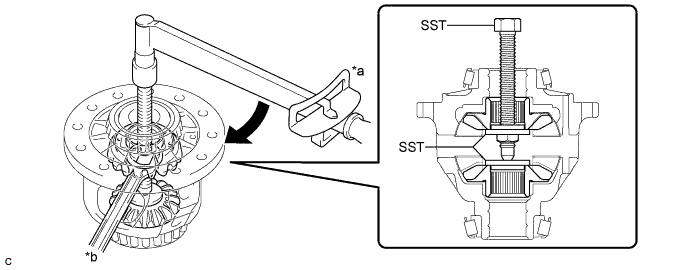
Text in Illustration *a Turn Using SST as shown in the illustration, rotate the front differential side gear to install the 2 front differential pinions and 2 front differential pinion thrust washers to the front differential case.
- SST
- 09528-52010 ( 09528-05030 )
CAUTION:
Be careful not to catch your fingers between the front differential pinion and front differential case.
Note
Do not drop the front differential pinion or front differential pinion thrust washer.
-
-
INSPECT FRONT DIFFERENTIAL PINION BACKLASH
-
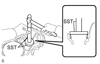
Install SST as shown in the illustration and tighten it.
Text in Illustration *a Turn *b Hold - SST
- 09528-52010 ( 09528-05010, 09953-05010 )
- Torque:
- 10 N*m { 102 kgf*cm, 7 ft.*lbf }
-
Secure the front differential case in a vise between aluminum plates.
Note
Do not overtighten the vise.
-
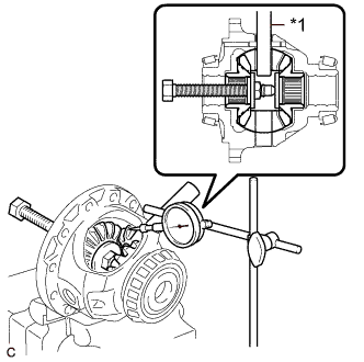
Text in Illustration *1 Front No. 1 Differential Pinion Shaft Install the front No. 1 differential pinion shaft to the front differential pinion as shown in the illustration.
-
Using a dial indicator, measure the front differential pinion backlash.
Standard Backlash 0.15 mm (0.00591 in.) or less Tech Tips
Select front No. 1 differential side gear thrust washers of the same thickness for both the right and left side.
If the backlash is not as specified, replace the front No. 1 differential side gear thrust washers with washers of a different thickness. Use the table below to select a front No. 1 differential side gear thrust washer which will ensure that the backlash is within the specification.
Front No. 1 Differential Side Gear Thrust Washer Thickness: Part No. Thickness (mm (in.)) 41361-33020 1.50 (0.0591) 41361-33030 1.55 (0.0610) 41361-33040 1.60 (0.0630) 41361-33050 1.65 (0.0650) 41361-33060 1.70 (0.0669) 41361-33070 1.75 (0.0689) 41361-33080 1.80 (0.0709) 41361-33090 1.85 (0.0728) 41361-33100 1.90 (0.0748)
-
-
INSTALL FRONT NO. 1 DIFFERENTIAL PINION SHAFT
-
Coat the front No. 1 differential pinion shaft with ATF.
Text in Illustration ATF -
Install the front No. 1 differential pinion shaft to the front differential case so that the hole for the front differential pinion shaft straight pin is aligned with the hole in the front differential case.
-
-
INSPECT FRONT DIFFERENTIAL CASE
-
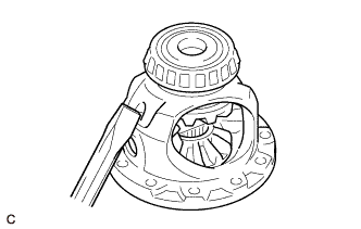
Using SST, rotate the front differential side gear as shown in the illustration.
- SST
- 09528-52010 ( 09528-05030 )
Standard The front differential side gear does not lock when rotated in either direction.
-
If the front differential side gear locks, perform all inspections.
-
If the front differential side gear still locks even after replacing the malfunctioning parts, replace the front differential case.
-
Replace any parts that do not meet the specification.
-
-
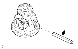
INSTALL FRONT DIFFERENTIAL PINION SHAFT STRAIGHT PIN
-
Using a 5 mm pin punch and a hammer, install the front differential pinion shaft straight pin to the front differential case.
-
Using a chisel and hammer, stake the front differential case.
-
-
ADJUST DIFFERENTIAL SIDE BEARING PRELOAD
-
Remove any remaining seal packing from the contact surfaces of the transaxle housing and transaxle case sub-assembly.
-
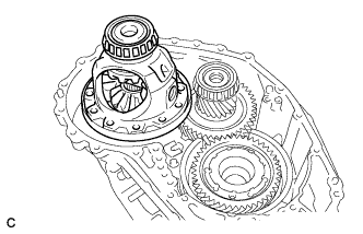
Install the front differential case to the transaxle case sub-assembly.
-
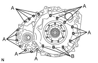
Install the transaxle housing to the transaxle case sub-assembly with the 20 bolts.
- Torque:
- Bolt (A)
- 31 N*m { 312 kgf*cm, 23 ft.*lbf }
- Bolt (B)
- 23 N*m { 231 kgf*cm, 17 ft.*lbf }
-
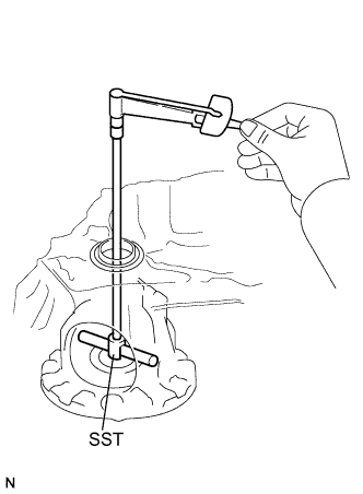
Using SST, turn the front differential case right and left 2 or 3 times to settle the bearings.
- SST
- 09564-33010
-
Using SST and a torque wrench, measure the turning torque of the differential side bearing while rotating SST at 10 rpm.
- SST
- 09564-33010
Turning Torque 0.8 to 1.4 N*m (8 to 14 kgf*cm, 7 to 12 in.*lbf) If the turning torque is not within the specified range, refer to the table below to select a shim so that the turning torque is within the specified range.
Shim Thickness Part No. Thickness
(mm (in.))
90564-79054 2.000 (0.0787) 90564-79055 2.025 (0.0797) 90564-79056 2.050 (0.0807) 90564-79057 2.075 (0.0817) 90564-79058 2.100 (0.0827) 90564-79059 2.125 (0.0837) 90564-79060 2.150 (0.0846) 90564-79061 2.175 (0.0856) 90564-79062 2.200 (0.0866) 90564-79063 2.225 (0.0876) 90564-79064 2.250 (0.0886) 90564-79065 2.275 (0.0896) 90564-79066 2.300 (0.0906) 90564-79067 2.325 (0.0915) 90564-79068 2.350 (0.0925) 90564-79069 2.375 (0.0935) 90564-79070 2.400 (0.0945) 90564-79071 2.425 (0.0955) 90564-79072 2.450 (0.0965) 90564-79073 2.475 (0.0974) 90564-79074 2.500 (0.0984) 90564-79075 2.525 (0.0994) 90564-79076 2.550 (0.100) 90564-79077 2.575 (0.101) 90564-79078 2.600 (0.102) 90564-79079 2.625 (0.103) 90564-79080 2.650 (0.104) 90564-79081 2.675 (0.105) 90564-79082 2.700 (0.106) 90564-79083 2.725 (0.107) 90564-79084 2.750 (0.108) 90564-79085 2.775 (0.109) 90564-79086 2.800 (0.110) 90564-79087 2.825 (0.111) 90564-79088 2.850 (0.112) 90564-79089 2.875 (0.113) -
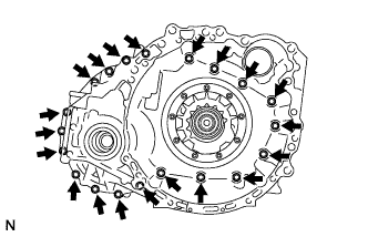
Remove the 20 bolts and transaxle housing from the transaxle case sub-assembly.
-
Remove the front differential case from the transaxle case sub-assembly.
-
-
INSTALL FRONT DIFFERENTIAL RING GEAR
-
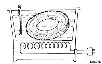
Using ATF and a heater, heat the front differential ring gear to 90 to 110°C (194 to 230°F).
Note
Do not heat the front differential ring gear to more than 110°C (230°F).
-
Clean the contact surface of the front differential case.
-
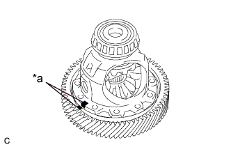
Text in Illustration *a Matchmark Align the matchmarks, and install the front differential ring gear to the front differential case quickly.
-
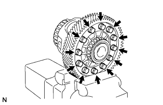
Install the 12 bolts.
- Torque:
- 120 N*m { 1224 kgf*cm, 89 ft.*lbf }
Note
-
Tighten the bolts after the front differential ring gear has cooled down sufficiently.
-
Tighten the bolts evenly in a diagonal pattern using several steps.
-
-
INSTALL TRANSAXLE CASE OIL SEAL
-
Coat the lip of a new transaxle case oil seal with MP grease.
-
Using SST and a hammer, install the transaxle case oil seal to the transaxle case sub-assembly.
- SST
- 09316-10010
- 09950-70010 ( 09951-07100 )
Standard Depth -0.5 to 0.5 mm (-0.0197 to 0.0197 in.) Note
Make sure that the transaxle case oil seal is installed in the correct direction.
Do not damage the lip of the transaxle case oil seal.
-
-
INSTALL FRONT TRANSAXLE CASE OIL SEAL
-
Coat the lip of a new front transaxle case oil seal with MP grease.
-
Using SST and a hammer, install the front transaxle case oil seal to the transaxle housing.
- SST
- 09308-14010
Standard Depth -0.5 to 0.5 mm (-0.0197 to 0.0197 in.) Note
Make sure that the front transaxle case oil seal is installed in the correct direction.
Do not damage the lip of the front transaxle case oil seal.
-