AUTOMATIC TRANSAXLE UNIT REASSEMBLY

-
BEARING POSITION
-
Check each bearing position and installation direction.
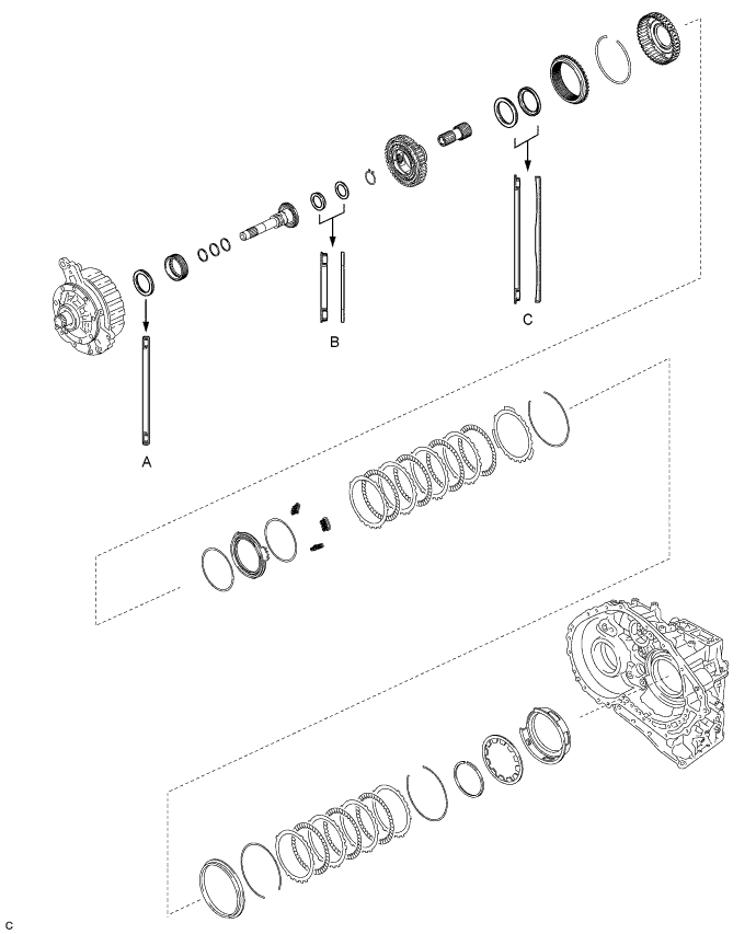
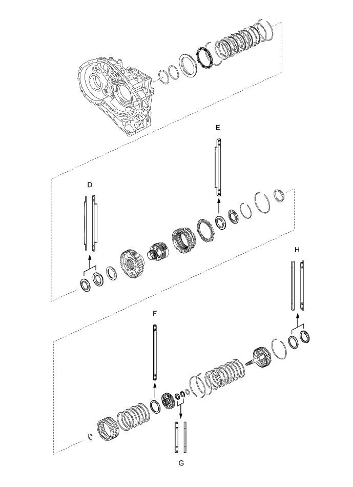
Mark Front Race Diameter
Inside / Outside mm (in.)
Thrust Bearing Diameter
Inside / Outside mm (in.)
Rear Race Diameter
Inside / Outside mm (in.)
A - 57.7 (2.27) / 75.2 (2.96) - B - 29.1 (1.15) / 48.6 (1.91) 30.7 (1.21) / 48.3 (1.90) C - 62.6 (2.47) / 82.4 (3.24) 65.9 (2.59) / 80.3 (3.16) D 59.4 (2.34) / 77 (3.03) 53.1 (2.09) / 79 (3.11) - E - 56.1 (2.21) / 80.9 (3.19) - F - 61.2 (2.41) / 79 (3.11) - G - 28 (1.10) / 47.1 (1.85) 26.1 (1.03) / 44 (1.73) H 52.2 (2.06) / 70.4 (2.77) 48.9 (1.93) / 72.0 (2.84) -
-
-
INSTALL COUNTER DRIVE GEAR BEARING
Note
Perform this procedure only when replacement of the counter drive gear bearing or transaxle case sub-assembly is necessary.
-
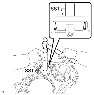
Using SST and a press, install a new counter drive gear bearing (outer race) and a new snap ring to the transaxle case sub-assembly.
- SST
- 09950-60020 ( 09951-01030 )
- 09950-70010 ( 09951-07100 )
-
-
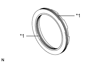
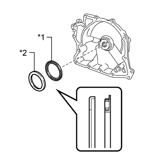
INSTALL COUNTER DRIVEN GEAR REAR TAPERED ROLLER BEARING OUTER RACE
-
Using SST and a hammer, install a new counter driven gear rear tapered roller bearing outer race to the transaxle case sub-assembly.
- SST
- 09950-60010 ( 09951-00650 )
- 09950-70010 ( 09951-07100 )
Note
Make sure to install the counter driven gear rear tapered roller bearing outer race so that there is no clearance between the counter driven gear rear tapered roller bearing outer race and transaxle case sub-assembly. If there is any clearance, the turning torque of the counter driven gear cannot be measured correctly.
-
-
INSTALL COUNTER DRIVEN GEAR FRONT TAPERED ROLLER BEARING OUTER RACE
-
Install the shim to the transaxle housing.
-
Using SST, install a new counter driven gear front tapered roller bearing outer race to the transaxle housing.
- SST
- 09950-60020 ( 09951-00810 )
- 09950-70010 ( 09951-07100 )
Note
Make sure to install the counter driven gear front tapered roller bearing outer race so that there is no clearance between the counter driven gear front tapered roller bearing outer race, shim and transaxle housing. If there is any clearance, the turning torque of the counter driven gear cannot be measured correctly.
-
-
INSTALL COUNTER DRIVEN GEAR REAR TAPERED ROLLER BEARING
-
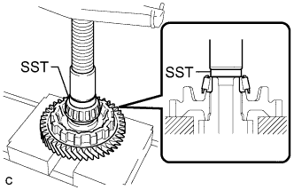
Using SST and a press, install a new counter driven gear rear tapered roller bearing to the counter driven gear.
- SST
- 09950-60010 ( 09951-00420 )
Note
Make sure to install the counter driven gear rear tapered roller bearing so that there is no clearance between the counter driven gear rear tapered roller bearing and counter driven gear. If there is any clearance, the turning torque of the counter driven gear cannot be measured correctly.
-
-
INSTALL COUNTER DRIVEN GEAR FRONT TAPERED ROLLER BEARING
-
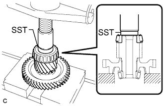
Using SST and a press, install a new counter driven gear front tapered roller bearing to the counter driven gear.
- SST
- 09950-60010 ( 09951-00530 )
Note
Make sure to install the counter driven gear front tapered roller bearing so that there is no clearance between the counter driven gear front tapered roller bearing and counter driven gear. If there is any clearance, the turning torque of the counter driven gear cannot be measured correctly.
-
-
ADJUST COUNTER DRIVEN GEAR PRELOAD
-
Remove any remaining seal packing from the contact surfaces of the transaxle housing and transaxle case sub-assembly.
-
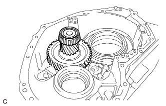
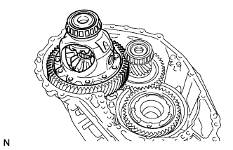
Install the counter driven gear to the transaxle case sub-assembly.
-
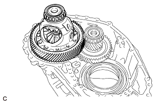
Install the front differential case to the transaxle case sub-assembly.
-
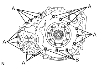
Install the transaxle housing to the transaxle case sub-assembly with the 20 bolts.
- Torque:
- Bolt (A)
- 31 N*m { 316 kgf*cm, 23 ft.*lbf }
- Bolt (B)
- 23 N*m { 235 kgf*cm, 17 ft.*lbf }
-
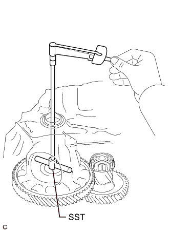
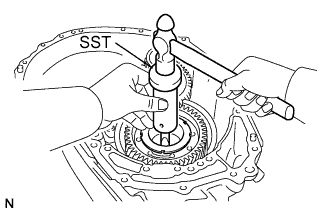
Using SST and a torque wrench, measure the turning torque of the counter driven gear while rotating SST at 10 rpm.
- SST
- 09564-33010
Turning Torque Differential side bearing preload + 2.2 to 4.1 N*m (22 to 42 kgf*cm, 19 to 36 in.*lbf) If the turning torque is not within the specified range, refer to the table below to select a shim for the counter driven gear front tapered roller bearing outer race so that the turning torque is within the specified range.
Shim Thickness: mm (in.) Thickness Thickness Thickness Thickness 2.000 (0.0787) 2.275 (0.0896) 2.525 (0.0994) 2.775 (0.109) 2.025 (0.0797) 2.300 (0.0906) 2.550 (0.100) 2.800 (0.110) 2.050 (0.0807) 2.325 (0.0915) 2.575 (0.101) 2.825 (0.111) 2.075 (0.0817) 2.350 (0.0925) 2.600 (0.102) 2.850 (0.112) 2.100 (0.0827) 2.375 (0.0935) 2.625 (0.103) 2.875 (0.113) 2.125 (0.0837) 2.400 (0.0945) 2.650 (0.104) 2.900 (0.114) 2.150 (0.0846) 2.425 (0.0955) 2.675 (0.105) 2.925 (0.115) 2.175 (0.0856) 2.450 (0.0965) 2.700 (0.106) 2.950 (0.116) 2.200 (0.0866) 2.475 (0.0974) 2.725 (0.107) 2.975 (0.117) 2.225 (0.0876) 2.500 (0.0984) 2.750 (0.108) 3.000 (0.118) 2.250 (0.0886) - - - -
Remove the 20 bolts and transaxle housing from the transaxle case sub-assembly.
-
Remove the front differential case from the transaxle case sub-assembly.
-
Remove the counter driven gear from the transaxle case sub-assembly.
-
-
INSTALL MANUAL VALVE LEVER SHAFT OIL SEAL
-
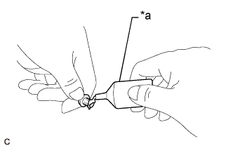
Coat the lip of a new manual valve lever shaft oil seal with MP grease.
-
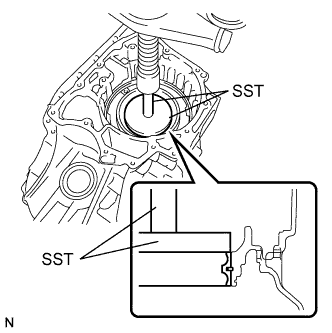
Using SST and a hammer, install the manual valve lever shaft oil seal to the transaxle case sub-assembly.
- SST
- 09950-60010 ( 09951-00230 )
- 09950-70010 ( 09951-07100 )
Standard Depth -0.5 to 0.5 mm (-0.0197 to 0.0197 in.)
-
-
INSTALL MANUAL VALVE LEVER SHAFT SUB-ASSEMBLY
-
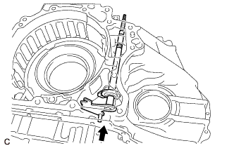
Install the manual valve lever shaft sub-assembly to the transaxle case sub-assembly.
Note
Do not damage the manual valve lever shaft oil seal while installing the manual valve lever shaft sub-assembly to the transaxle case sub-assembly.
-
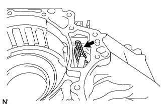
Using needle-nose pliers, install the manual valve lever shaft retainer spring to the manual valve lever shaft sub-assembly.
-
-
INSTALL PARKING LOCK ROD SUB-ASSEMBLY
-
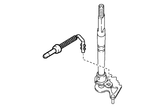
Align the protrusions with the notches on the manual valve lever shaft sub-assembly and install the parking lock rod sub-assembly.
-
-
INSTALL MANUAL DETENT SPRING SUB-ASSEMBLY
-
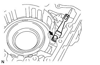
Install the manual detent spring sub-assembly and cover to the transaxle case sub-assembly with the bolt.
- Torque:
- 23 N*m { 235 kgf*cm, 17 ft.*lbf }
Note
Make sure to install the manual detent spring sub-assembly first and then the cover.
-
-
INSTALL NO. 3 BRAKE PISTON
-
Coat the lip of the No. 3 brake piston with ATF.
-
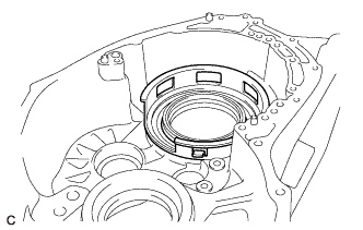
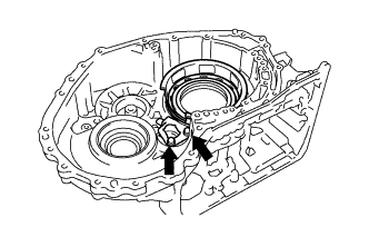
Temporarily install the No. 3 brake piston to the transaxle case sub-assembly.
-
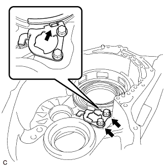
Temporarily install the pawl stopper plate to the transaxle case sub-assembly with the 2 bolts.
Note
After installing, make sure that the protrusions on the No. 3 brake piston and grooves on the pawl stopper plate are aligned.
-
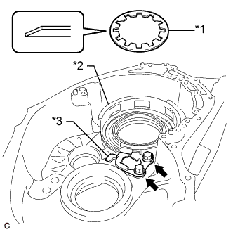
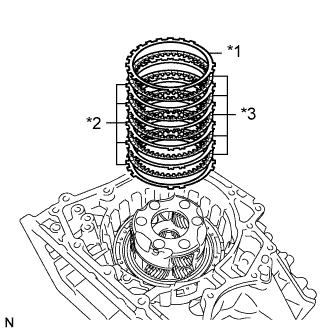
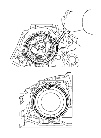
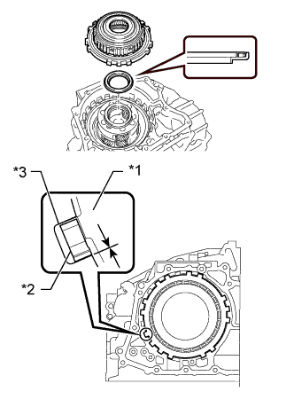
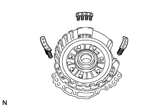
Text in Illustration *1 Brake Piston Return Spring *2 No. 3 Brake Piston *3 Pawl Stopper Plate Press the No. 3 brake piston into the transaxle case sub-assembly.
Note
Make sure that the lip of the No. 3 brake piston is not twisted and does not get caught in the transaxle case sub-assembly.
Tech Tips
Use the installation surface of the brake piston return spring to press the No. 3 brake piston into the transaxle case sub-assembly.
-
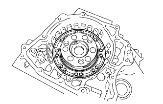
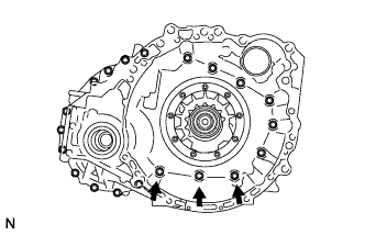
Install the brake piston return spring to the transaxle case sub-assembly.
Note
Install the brake piston return spring as shown in the illustration.
-
Remove the 2 bolts and pawl stopper plate from the transaxle case sub-assembly.
-
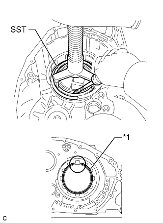
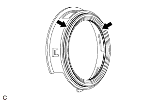
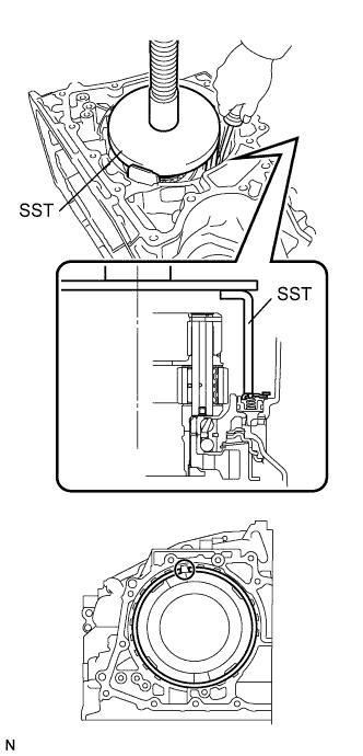
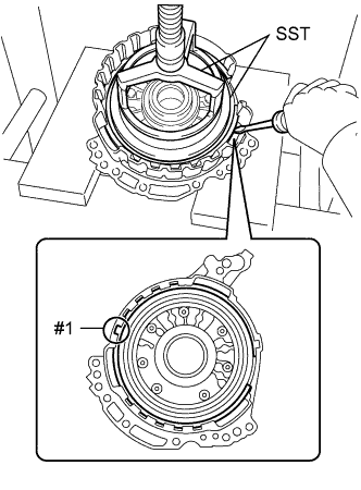
Text in Illustration *1 Snap Ring Place SST on the brake piston return spring and compress the brake piston return spring using a press.
- SST
- 09387-00070
Note
Stop the press when the brake piston return spring is flush with the snap ring groove. This prevents the brake piston return spring from being deformed.
-
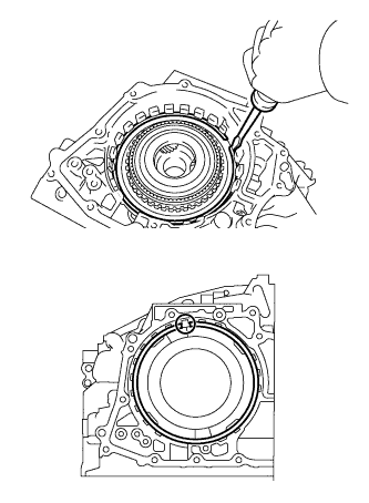
Using a screwdriver, install the snap ring to the transaxle case sub-assembly as shown in the illustration.
Note
-
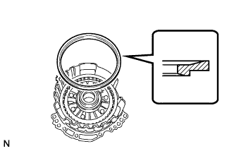
Confirm that the snap ring is correctly located in the groove of the transaxle case sub-assembly.
-
Be sure to orient the snap ring so that the edges do not protrude into one of the cutouts on the brake piston return spring as shown in the illustration.
-
-
-
INSTALL COUNTER DRIVE GEAR
-
Install 2 new balls of the counter drive gear bearing to the counter drive gear bearing.
-
Using SST, install the counter drive gear, a new bearing inner race (front side) and bearing inner race (rear side) to the transaxle case sub-assembly.
- SST
- 09223-15030
- 09527-17011 ( 09951-00810 )
- 09950-70010 ( 09951-07100 )
Note
There should not be any clearance between the bearing inner race (front side) and counter drive gear.
-
-
INSTALL FRONT PLANETARY GEAR ASSEMBLY
-
Using SST and a press, install the front planetary gear assembly to the transaxle case sub-assembly.
- SST
- 09223-15030
- 09527-17011
- 09951-01100
-
-
INSTALL NO. 2 BRAKE PISTON
-
Text in Illustration *1 O-ring Coat 2 new O-rings with ATF and install them to the No. 2 brake piston.
Note
Ensure that the O-rings are not twisted.
-
Install the No. 2 brake piston to the transaxle case sub-assembly.
Note
Be careful not to damage the O-rings.
-
-
INSTALL 1ST AND REVERSE BRAKE RETURN SPRING SUB-ASSEMBLY
-
Install the 1st and reverse brake return spring sub-assembly to the transaxle case sub-assembly.
-
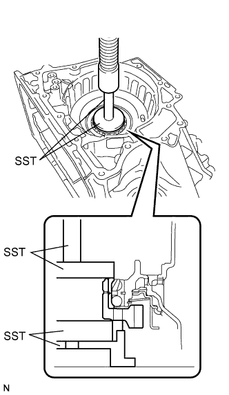
Place SST on the 1st and reverse brake return spring sub-assembly and compress the 1st and reverse brake return spring sub-assembly using a press.
- SST
- 09387-00060
Note
Stop the press when the 1st and reverse brake return spring sub-assembly is flush with the snap ring groove. This prevents the 1st and reverse brake return spring sub-assembly from being deformed.
-
Using a screwdriver, install the snap ring to the transaxle case sub-assembly as shown in the illustration.
Note
-
Confirm that the snap ring is correctly located in the groove of the transaxle case sub-assembly.
-
Be sure to orient the snap ring so that the edges do not protrude into one of the cutouts on the transaxle case sub-assembly as shown in the illustration.
-
-
-
INSTALL NO. 2 BRAKE DISC
-
Text in Illustration *1 No. 2 Brake Flange *2 No. 2 Brake Plate *3 No. 2 Brake Disc Install the 5 No. 2 brake discs, 5 No. 2 brake plates and No. 2 brake flange to the transaxle case sub-assembly.
Note
Make sure that the No. 2 brake discs, No. 2 brake plates and No. 2 brake flange are installed in the correct order.
-
Using a screwdriver, install the snap ring to the transaxle case sub-assembly.
Note
-
Confirm that the snap ring is correctly located in the groove of the transaxle case sub-assembly.
-
Be sure to orient the snap ring so that the edges do not protrude into one of the cutouts on the transaxle case sub-assembly as shown in the illustration.
-
-
-
INSPECT CLEARANCE OF NO. 2 BRAKE
-
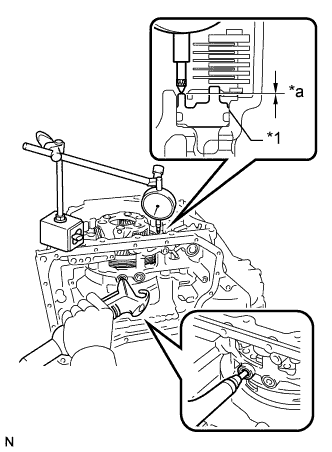
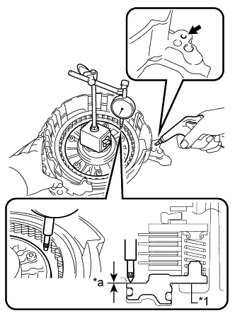
Text in Illustration *1 No. 2 Brake Piston *a Clearance Apply compressed air to the oil pressure supply hole shown in the illustration, and check the operation of the No. 2 brake piston.
-
Set a dial indicator as shown in the illustration.
-
Using a dial indicator, measure the clearance of the No. 2 brake while applying compressed air (200 kPa, 2.0 kgf/cm2, 29 psi).
Standard Clearance 0.884 to 1.196 mm (0.0348 to 0.0471 in.) Tech Tips
-
Measure the clearance at 3 points where the brake piston diameter is approximately 140 mm (5.51 in.) and calculate the average.
If the clearance is not as specified, select an appropriate No. 2 brake flange so that the clearance will be within the specified range.
-
There are 5 No. 2 brake flanges of different thicknesses.
No. 2 Brake Flange Thickness: mm (in.) Mark Thickness 40 4.0 (0.157) 41 4.1 (0.161) 42 4.2 (0.165) 43 4.3 (0.169) 44 4.4 (0.173) -
-
-
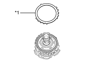
INSTALL PLANETARY RING GEAR FLANGE
-
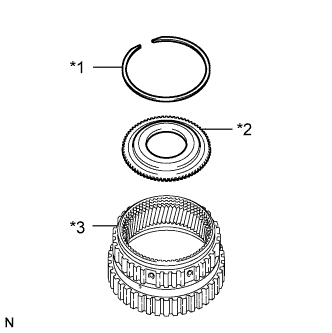
Text in Illustration *1 Snap Ring *2 Planetary Ring Gear Flange *3 Planetary Ring Gear Install the planetary ring gear flange to the planetary ring gear.
-
Using a screwdriver, install the snap ring to the planetary ring gear.
Note
Confirm that the snap ring is correctly located in the groove of the planetary ring gear.
-
-
INSTALL PLANETARY RING GEAR
-
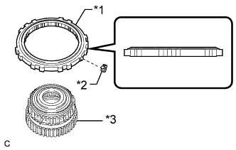
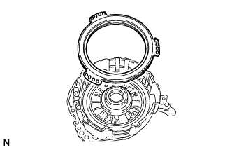
Text in Illustration *1 One-way Clutch Assembly *2 Outer Race Retainer *3 Planetary Ring Gear Install the outer race retainer to the one-way clutch assembly.
-
Install the planetary ring gear to the one-way clutch assembly.
Note
Make sure that the one-way clutch assembly is positioned in the correct direction as shown in the illustration.
-
-
INSTALL ONE-WAY CLUTCH ASSEMBLY
-
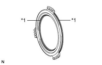
Text in Illustration *1 One-way Clutch Assembly *2 Outer Race Retainer *3 Transaxle Case Sub-assembly Coat the thrust needle roller bearing with ATF and install it to the front planetary gear assembly.
Bearing Diameter: mm (in.) - Inside Outside Bearing 56.1 (2.21) 80.9 (3.19) Note
Be sure to install the thrust needle roller bearing so that the temper colored side of the race is visible.
-
Install the one-way clutch assembly with planetary ring gear to the transaxle case sub-assembly.
Note
-
Make sure that there is no clearance between the outer race retainer and claw on the one-way clutch assembly. If there is any clearance, the spring of the retainer will be deformed.
-
Ensure that there is no clearance between the one-way clutch assembly and transaxle case sub-assembly.
-
-
Using a screwdriver, install the snap ring to the transaxle case sub-assembly.
Note
-
Confirm that the snap ring is correctly located in the groove of the transaxle case sub-assembly.
-
Be sure to orient the snap ring so that the edges do not protrude into one of the cutouts on the transaxle case sub-assembly as shown in the illustration.
-
-
-
INSTALL PARKING LOCK PAWL
-
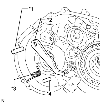
Text in Illustration *1 Parking Lock Pawl Shaft *2 Parking Lock Pawl *3 Spring *4 Parking Lock Pawl Pin Install the parking lock pawl to the transaxle case sub-assembly with the parking lock pawl shaft.
-
Install the parking lock pawl pin to the transaxle case sub-assembly.
-
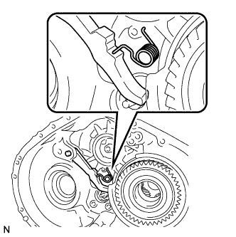
Install the spring to the parking lock pawl.
Note
Make sure that one end of the spring is set in the hole of the transaxle case sub-assembly and the other end is positioned on the parking lock pawl as shown in the illustration.
-
-
INSTALL PARKING LOCK SLEEVE
-
Install the parking lock sleeve to the transaxle case sub-assembly.
-
-
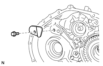
INSTALL PAWL STOPPER PLATE
-
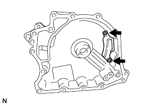
Install the pawl stopper plate to the transaxle case sub-assembly with the 2 bolts.
- Torque:
- 23 N*m { 235 kgf*cm, 17 ft.*lbf }
-
-
INSTALL PAWL SHAFT CLAMP
-
Install the pawl shaft clamp to the transaxle case sub-assembly with the bolt.
- Torque:
- 23 N*m { 235 kgf*cm, 17 ft.*lbf }
-
-
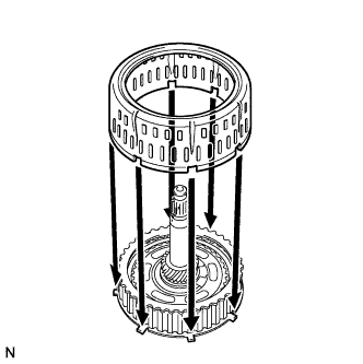
INSTALL COUNTER DRIVEN GEAR
-
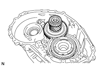
Install the counter driven gear to the transaxle case sub-assembly.
-
-
INSTALL COUNTER DRIVE GEAR NUT
-
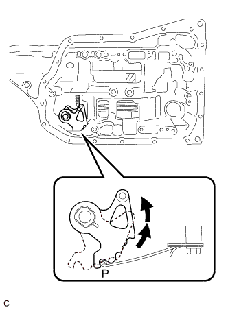
Turn the manual valve lever shaft sub-assembly 2 notches counterclockwise to set it to the P position as shown in the illustration.
-
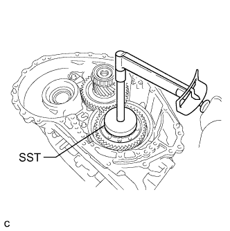
Using SST, install a new counter drive gear nut to the front planetary gear assembly.
- SST
- 09387-00130
- Torque:
- 120 N*m { 1224 kgf*cm, 89 ft.*lbf }
-
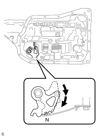
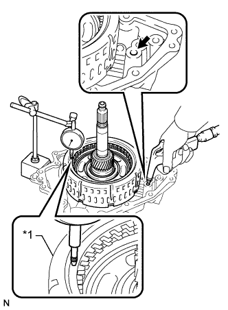
Turn the manual valve lever shaft sub-assembly 2 notches clockwise to set it to the N position as shown in the illustration.
-
Remove the counter driven gear from the transaxle case sub-assembly.
-
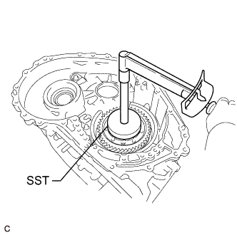
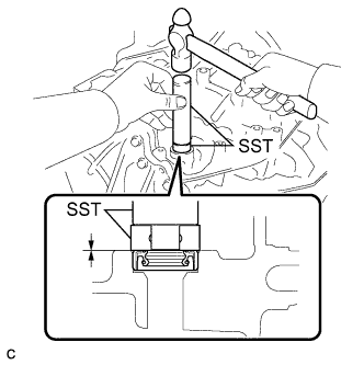
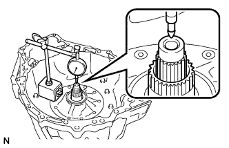
Using SST and a torque wrench, measure the turning torque of the bearing while rotating SST at 60 rpm.
- SST
- 09387-00130
Turning Torque 0.1 to 0.2 N*m (1 to 2 kgf*cm, 0.9 to 1.9 in.*lbf) If the measured value is not within the specified range, gradually tighten the counter drive gear nut until the turning falls within the specified range.
Maximum Torque 180 N*m (1835 kgf*cm, 133 ft.*lbf) -
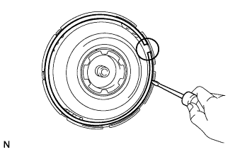
Using SST and a hammer, stake the front planetary gear assembly.
- SST
- 09930-00010
-
Install the counter driven gear to the transaxle case sub-assembly.
-
-
INSTALL FRONT DIFFERENTIAL CASE
-
Install the front differential case to the transaxle case sub-assembly.
-
-
INSTALL NO. 1 BRAKE PISTON
-
Text in Illustration *1 O-ring Coat 2 new O-rings with ATF and install them to the No. 1 brake piston.
Note
Ensure that the O-rings are not twisted.
-
Install the No. 1 brake piston to the front oil pump assembly.
Note
Be careful not to damage the O-rings.
-
-
INSTALL 2ND BRAKE PISTON RETURN SPRING SUB-ASSEMBLY
-
Install the 3 2nd brake piston return spring sub-assemblies to the front oil pump assembly.
Note
Make sure that the 3 2nd brake piston return spring sub-assemblies are installed to the protrusions on the front oil pump assembly.
-
-
INSTALL NO. 1 BRAKE DISC
-
Text in Illustration *1 No. 1 Brake Flange *2 No. 1 Brake Plate *3 No. 1 Brake Disc Install the 4 No. 1 brake discs, 4 No. 1 brake plates and No. 1 brake flange to the front oil pump assembly.
Note
-
Make sure that the No. 1 brake discs, No. 1 brake plates, and No. 1 brake flange are installed in the correct order.
-
Be sure to install the No. 1 brake flange in the correct direction.
-
-
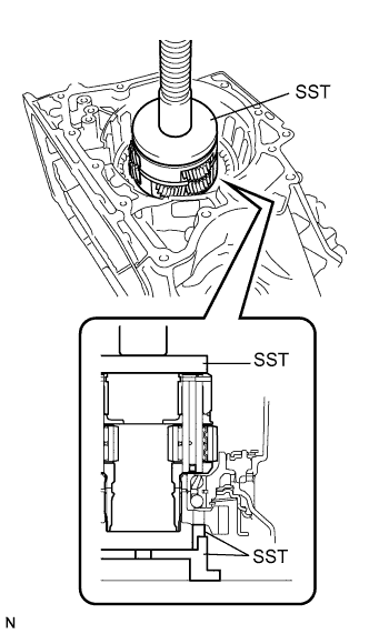
Place SST on the No. 1 brake flange and compress the No. 1 brake flange using a press.
- SST
- 09387-00070
- 09495-65040
Note
Stop the press when the 2nd brake piston return spring sub-assemblies are flush with the snap ring groove. This prevents the 2nd brake piston return spring sub-assemblies from being deformed.
-
Using a screwdriver, install the snap ring to the front oil pump assembly as shown in the illustration (#1).
Note
-
Confirm that the snap ring is correctly located in the groove of the front oil pump assembly.
-
Make sure to align the protruding part of the snap ring with the cutout (#1) of the front oil pump assembly shown in the illustration to install the snap ring.
-
-
Install the brake snap ring stopper to the front oil pump assembly.
Note
Be sure to install the brake snap ring stopper in the correct direction.
-
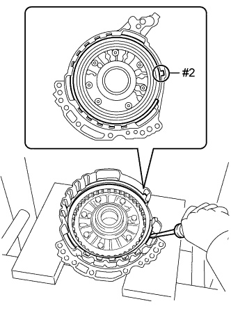
Using a screwdriver, install the snap ring to the front oil pump assembly as shown in the illustration (#2).
Note
-
Confirm that the snap ring is correctly located in the groove of the front oil pump assembly.
-
Make sure to align the protruding part of the snap ring with the cutout (#2) of the front oil pump assembly shown in the illustration to install the snap ring.
-
-
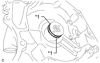
Text in Illustration *1 Snap Ring *2 Brake Snap Ring Stopper *a Correctly Installed Check that the brake snap ring stopper can be turned by hand.
Note
If the brake snap ring stopper cannot be turned by hand, the brake snap ring stopper may have been installed upside down, or a snap ring may not have been completely located in the groove on the front oil pump assembly. Remove and reinstall the snap ring and the brake snap ring stopper.
-
-
INSPECT CLEARANCE OF NO. 1 BRAKE
-
Text in Illustration *1 No. 1 Brake Piston *a Clearance Apply compressed air to the oil pressure supply hole shown in the illustration, and check the operation of the No. 1 brake piston.
-
Set a dial indicator as shown in the illustration.
-
Using a dial indicator, measure the clearance of the No. 1 brake while applying compressed air (200 kPa, 2.0 kgf/cm2, 29 psi).
Standard Clearance 0.807 to 0.974 mm (0.0318 to 0.0383 in.) Tech Tips
-
Measure the clearance at 3 points where the brake piston diameter is approximately 140 mm (5.51 in.) and calculate the average.
If the clearance is not as specified, select an appropriate No. 1 brake flange so that the clearance will be within the specified range.
-
There are 7 No. 1 brake flanges of different thicknesses.
No. 1 Brake Flange Thickness: mm (in.) Mark Thickness 30 3.0 (0.118) 31 3.1 (0.122) 32 3.2 (0.126) 33 3.3 (0.130) 34 3.4 (0.134) 35 3.5 (0.138) 36 3.6 (0.142) -
-
-
INSTALL UNDERDRIVE PLANETARY SUN GEAR
-
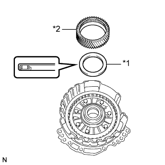
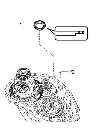
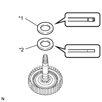
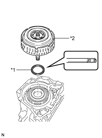
Text in Illustration *1 Thrust Needle Roller Bearing *2 Underdrive Planetary Sun Gear Coat the thrust needle roller bearing with ATF and install it to the front oil pump assembly.
Bearing Diameter: mm (in.) - Inside Outside Bearing 57.7 (2.27) 75.2 (2.96) Note
Be sure to install the thrust needle roller bearing so that the temper colored side of the race is visible.
-
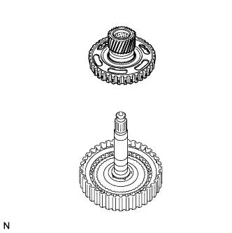
Install the underdrive planetary sun gear to the front oil pump assembly.
-
-
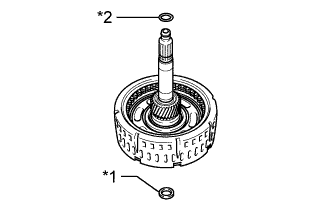
INSTALL INPUT SHAFT SUB-ASSEMBLY
-
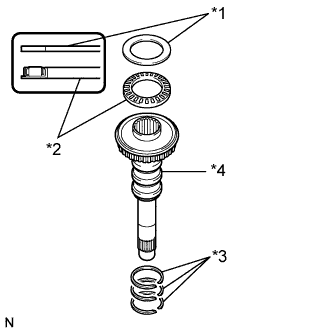
Text in Illustration *1 Thrust Needle Roller Race *2 Thrust Needle Roller Bearing *3 Input Shaft Oil Seal Ring *4 Input Shaft Sub-assembly Coat 3 new input shaft oil seal rings with ATF and install them to the input shaft sub-assembly.
Note
Do not expand the gap of the input shaft oil seal rings excessively.
-
Coat the thrust needle roller bearing and thrust needle roller race with ATF, and install them to the input shaft sub-assembly.
Bearing and Race Diameter: mm (in.) - Inside Outside Bearing 29.1 (1.15) 48.6 (1.91) Race 30.7 (1.21) 48.3 (1.90) Note
Be sure to install the thrust needle roller bearing in the correct direction.
-
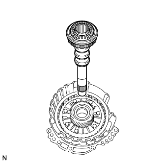
Install the input shaft sub-assembly to the front oil pump assembly.
-
-
INSTALL PLANETARY SUN GEAR SUB-ASSEMBLY
-
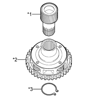
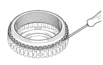
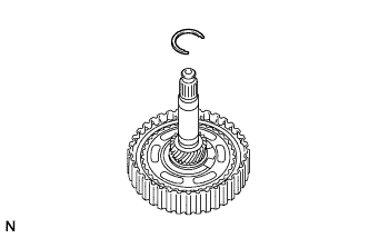
Text in Illustration *1 Planetary Sun Gear Sub-assembly *2 Underdrive Planetary Gear Assembly *3 Snap Ring Using a snap ring expander, install the snap ring to the underdrive planetary gear assembly.
-
Using a snap ring expander, install the planetary sun gear sub-assembly to the underdrive planetary gear assembly with the snap ring expanded.
-
-
INSTALL UNDERDRIVE PLANETARY RING GEAR
Tech Tips
Perform this procedure only when replacement of the underdrive planetary ring gear or No. 3 brake hub is necessary.
-
Install the snap ring to the underdrive planetary ring gear.
-
While compressing the snap ring with a screwdriver, install the underdrive planetary ring gear to the No. 3 brake hub.
Note
Confirm that the snap ring is correctly located in the groove of the No. 3 brake hub.
-
-
INSTALL NO. 3 BRAKE HUB
-
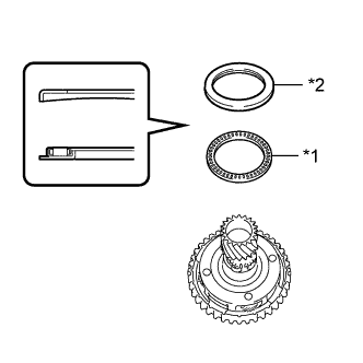
Text in Illustration *1 Thrust Needle Roller Bearing *2 Thrust Needle Roller Race Coat the thrust needle roller bearing and thrust needle roller race with ATF and install them to the underdrive planetary gear assembly.
Bearing and Race Diameter: mm (in.) - Inside Outside Bearing 62.6 (2.46) 82.4 (3.24) Race 65.9 (2.59) 80.3 (3.16) Note
Be sure to install the thrust needle roller bearing so that the temper colored side of the race is visible.
-
Install the No. 3 brake hub to the underdrive planetary gear assembly.
-
-
INSTALL UNDERDRIVE PLANETARY GEAR ASSEMBLY
-
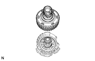
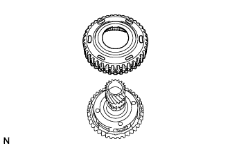
Install the underdrive planetary gear assembly to the front oil pump assembly.
-
-
INSTALL NO. 3 BRAKE DISC
-
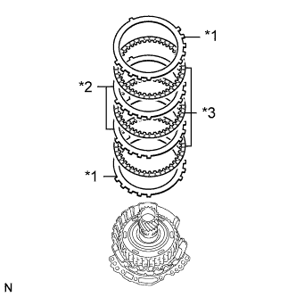
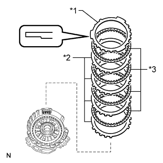
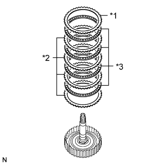
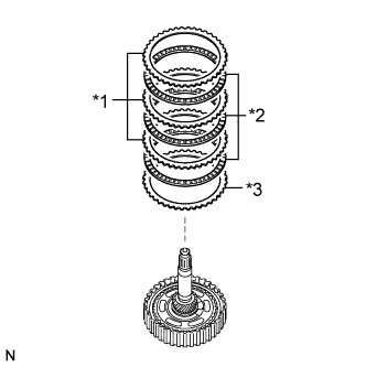
Text in Illustration *1 No. 3 Brake Flange *2 No. 3 Brake Plate *3 No. 3 Brake Disc Install the 2 No. 3 brake flanges, 3 No. 3 brake discs and 2 No. 3 brake plates to the front oil pump assembly.
Note
Make sure that the No. 3 brake discs, No. 3 brake plates and No. 3 brake flanges are installed in the correct order.
-
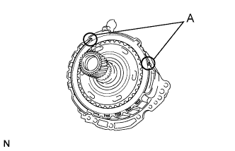
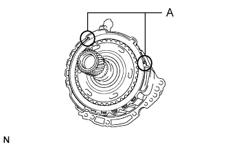
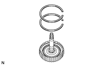
Using a screwdriver, install the snap ring to the front oil pump assembly.
Note
-
Confirm that the snap ring is correctly located in the groove of the front oil pump assembly.
-
Make sure that the snap ring ends are positioned as shown in the illustration (A).
-
-
-
INSPECT CLEARANCE OF NO. 3 BRAKE
-
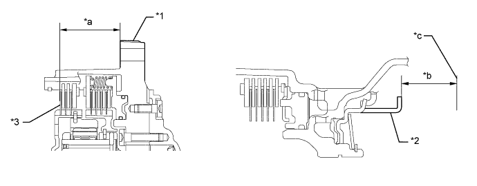
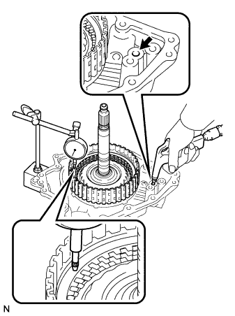
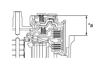
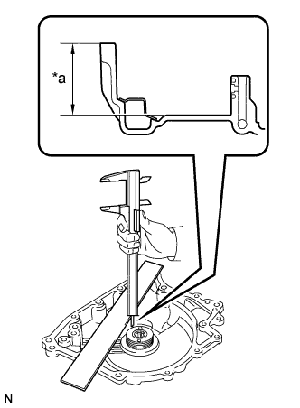
Using a vernier caliper and a straightedge, measure the distance shown in the illustration (Dimension (A)) while a load of 500 N (51 kgf, 112.4 lbf) is being applied to the flange.
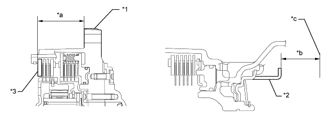
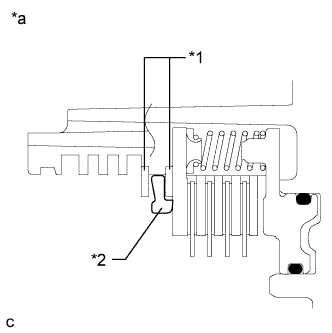
Text in Illustration *1 Front Oil Pump Assembly *2 No. 3 Brake Piston *3 No. 3 Brake Flange - - *a Dimension (A) *b Dimension (B) *c Contact Surface of Front Oil Pump Assembly - - Tech Tips
Measure the distance (Dimension (A)) at 3 points where the No. 3 brake flange diameter is approximately 166 mm (6.54 in.) and calculate the average.
-
Using a vernier caliper and a straightedge, measure the distance shown in the illustration (Dimension (B)).
Tech Tips
Measure the distance (Dimension (B)) at 3 points where the No. 3 brake piston diameter is approximately 166 mm (6.54 in.) and calculate the average.
-
Calculate the clearance value using the following formula:
Clearance = Dimension (B) - Dimension (A)
Standard Clearance 0.599 to 0.761 mm (0.0236 to 0.0300 in.) If the clearance is not as specified, select an appropriate No. 3 brake flange so that the clearance will be within the specified range.
-
Adjust clearance of No. 3 brake piston:
-
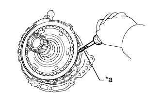
Text in Illustration *a Protective Tape Using a screwdriver with its tip wrapped with protective tape, remove the snap ring from the front oil pump assembly.
-
Text in Illustration *1 No. 3 Brake Flange Remove the No. 3 brake flange from the front oil pump assembly.
-
Using a vernier caliper and a straightedge, measure the distance shown in the illustration (Dimension (A)) while a load of 500 N (51 kgf, 112.4 lbf) is being applied to the No. 3 brake disc.
Text in Illustration *1 Front Oil Pump Assembly *2 No. 3 Brake Piston *3 No. 3 Brake Disc - - *a Dimension (A) *b Dimension (B) *c Contact Surface of Front Oil Pump Assembly - - Tech Tips
Measure the distance (Dimension (A)) at 3 points where the No. 3 brake disc diameter is approximately 166 mm (6.54 in.) and calculate the average.
-
Using a vernier caliper and a straightedge, measure the distance shown in the illustration (Dimension (B)).
Tech Tips
Measure the distance (Dimension (B)) at 3 points where the No. 3 brake piston diameter is approximately 166 mm (6.54 in.) and calculate the average.
-
Calculate the thickness of the replacement No. 3 brake flange using the following formula:
Thickness of Replacement No. 3 Brake Flange Dimension (B) - Dimension (A) - (0.599 to 0.761 mm (0.0236 to 0.0300 in.)) Tech Tips
There are 9 No. 3 brake flanges of different thicknesses.
No. 3 Brake Flange Thickness: mm (in.) Mark Thickness 37 3.7 (0.146) 38 3.8 (0.150) 39 3.9 (0.154) 40 4.0 (0.157) 41 4.1 (0.161) 42 4.2 (0.165) 43 4.3 (0.169) 44 4.4 (0.173) 45 4.5 (0.177) -
Text in Illustration *1 No. 3 Brake Flange Install the No. 3 brake flange to the front oil pump assembly.
-
Using a screwdriver with its tip wrapped with protective tape, install the snap ring to the front oil pump assembly.
Note
-
Confirm that the snap ring is correctly located in the groove of the front oil pump assembly.
-
Make sure that the snap ring ends are positioned as shown in the illustration (A).
-
-
-
-
INSTALL FRONT OIL PUMP BODY O-RING
-
Coat a new front oil pump body O-ring with ATF and install it to the front oil pump body sub-assembly.
-
-
INSTALL FRONT OIL PUMP ASSEMBLY
-
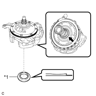
Text in Illustration *1 Thrust Needle Roller Bearing *2 O-ring Coat a new O-ring with ATF and install it to the transaxle case sub-assembly.
-
Coat the thrust needle roller bearing with ATF.
-
Install the thrust needle roller bearing to the counter drive gear nut.
Bearing and Race Diameter: mm (in.) - Inside Outside Bearing 53.1 (2.09) 79 (3.11) Note
Be sure to install the thrust needle roller bearing so that the temper colored side of the race is visible.
-
Coat the thrust needle roller race with MP grease.
-
Text in Illustration *1 Thrust Needle Roller Race Install the thrust needle roller race to the underdrive planetary gear assembly.
Bearing and Race Diameter: mm (in.) - Inside Outside Race 59.4 (2.34) 77 (3.03) -
Text in Illustration *1 Gasket Coat a new gasket with ATF and install it to the front oil pump assembly.
-
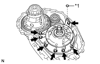
Install the front oil pump assembly to the transaxle case sub-assembly with the 7 bolts.
- Torque:
- 23 N*m { 235 kgf*cm, 17 ft.*lbf }
-
-
INSTALL DIFFERENTIAL GEAR LUBE APPLY TUBE
-
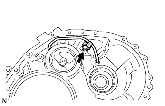
Install the differential gear lube apply tube to the transaxle housing.
Note
Insert the differential gear lube apply tube to the transaxle housing until it makes contact with the stopper.
-
Install the clamp to the differential gear lube apply tube with the bolt.
- Torque:
- 23 N*m { 235 kgf*cm, 17 ft.*lbf }
Note
There should be clearance between the differential gear lube apply tube and clamp.
-
-
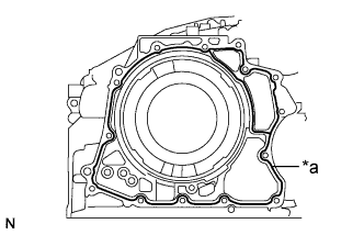
INSTALL TRANSAXLE HOUSING
-
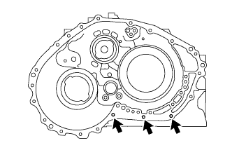
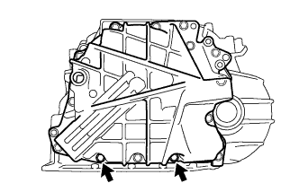
Clean and degrease the 3 bolts and installation holes in the transaxle case sub-assembly.
-
Remove any remaining seal packing from the contact surfaces of the transaxle housing and transaxle case sub-assembly.
Note
Make sure that there is no ATF on the contact surfaces of the transaxle housing and transaxle case sub-assembly.
-
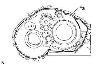
Text in Illustration *a FIPG Apply FIPG to the transaxle case sub-assembly.
FIPG Toyota Genuine Seal Packing 1281, Three Bond 1281 or equivalent Note
Apply FIPG in a continuous line (width 1.2 mm (0.0472 in.)) along the sealing surface of the transaxle case sub-assembly.
-
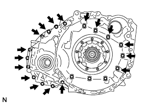
Install the transaxle housing to the transaxle case sub-assembly with the 17 bolts.
- Torque:
- 31 N*m { 316 kgf*cm, 23 ft.*lbf }
-
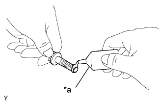
Text in Illustration *a Adhesive Apply adhesive to 2 or 3 threads on the ends of the 3 bolts.
Adhesive Toyota Genuine Adhesive 1324, Three Bond 1324 or equivalent Note
In order to ensure proper installation of the 3 bolts, apply adhesive to the 3 bolts and install them within 3 minutes of adhesive application.
-
Install the 3 bolts.
- Torque:
- 23 N*m { 235 kgf*cm, 17 ft.*lbf }
-
-
INSTALL NO. 1 CLUTCH DISC
-
Text in Illustration *1 No. 1 Clutch Flange *2 No. 1 Clutch Plate *3 No. 1 Clutch Disc Install the No. 1 clutch flange, 4 No. 1 clutch discs and 4 No. 1 clutch plates to the direct multiple disc clutch assembly.
Note
Make sure that the No. 1 clutch flange, No. 1 clutch discs and No. 1 clutch plates are installed in the correct order.
-
Using a screwdriver, install the 2 snap rings to the direct multiple disc clutch assembly.
Note
Confirm that the snap rings are correctly located in the groove of the direct multiple disc clutch assembly.
-
-
INSPECT CLEARANCE OF NO. 1 CLUTCH DISC
-
Install the direct multiple disc clutch assembly to the rear transaxle cover sub-assembly.
-
Using a dial indicator, measure the No. 1 clutch pack clearance while applying and releasing compressed air (200 kPa, 2.0 kgf/cm2, 29 psi).
Pack Clearance 0.806 to 0.974 mm (0.0317 to 0.0383 in.) Tech Tips
-
Measure the clearance at 3 points where the No. 1 clutch flange diameter is approximately 152 mm (5.98 in.) and calculate the average.
If the pack clearance is not as specified, select an appropriate No. 1 clutch flange so that the pack clearance will be within the specified range.
-
There are 6 No. 1 clutch flanges of different thicknesses.
No. 1 Clutch Flange Thickness: mm (in.) Mark Thickness 30 3.0 (0.118) 31 3.1 (0.122) 32 3.2 (0.126) 33 3.3 (0.130) 34 3.4 (0.134) 35 3.5 (0.138) -
-
-
INSTALL REAR PLANETARY SUN GEAR ASSEMBLY
-
Text in Illustration *1 Thrust Needle Roller Bearing *2 Thrust Needle Roller Race Coat the thrust needle roller bearing and thrust needle roller race with ATF and install them to the direct multiple disc clutch assembly.
Bearing and Race Diameter: mm (in.) - Inside Outside Bearing 28 (1.10) 47.1 (1.85) Race 26.1 (1.03) 44 (1.73) Note
Be sure to install the thrust needle roller bearing so that the temper colored side of the race is visible.
-
Install the rear planetary sun gear assembly to the direct multiple disc clutch assembly.
-
Using a snap ring expander, install the snap ring to the direct multiple disc clutch assembly.
-
-
INSTALL NO. 2 CLUTCH DISC
-
Text in Illustration *1 No. 2 Clutch Plate *2 No. 2 Clutch Disc *3 No. 2 Clutch Flange Install the No. 2 clutch flange, 3 No. 2 clutch discs and 3 No. 2 clutch plates to the direct multiple disc clutch assembly.
Note
Make sure that the No. 2 clutch flange, No. 2 clutch discs and No. 2 clutch plates are installed in the correct order.
-
-
INSTALL DIRECT MULTIPLE DISC CLUTCH SNAP RING
-
Install the No. 2 direct clutch piston to the direct multiple disc clutch assembly.
Note
Be sure to engage the claws on the direct multiple disc clutch assembly in the grooves on the No. 2 direct clutch piston.
-
Using a screwdriver, install the direct multiple disc clutch snap ring to the direct multiple disc clutch assembly.
Note
-
Position the opening of the direct multiple disc clutch snap ring as shown in the illustration.
-
Confirm that the direct multiple disc clutch snap ring is correctly located in the groove of the direct multiple disc clutch assembly.
-
-
-
INSPECT CLEARANCE OF NO. 2 CLUTCH DISC
-
Install the direct multiple disc clutch assembly to the rear transaxle cover sub-assembly.
-
Text in Illustration *1 No. 2 Direct Clutch Piston Using a dial indicator, measure the No. 2 clutch pack clearance while applying and releasing compressed air (200 kPa, 2.0 kgf/cm2, 29 psi).
Pack Clearance 0.544 to 0.744 mm (0.0214 to 0.0293 in.) Tech Tips
-
Measure the clearance at 3 points where the diameter of the No. 2 direct clutch piston is approximately 152 mm (5.98 in.) and calculate the average.
If the pack clearance is not as specified, select an appropriate No. 2 clutch flange so that the pack clearance will be within the specified range.
-
There are 6 No. 2 clutch flanges of different thicknesses.
No. 2 Clutch Flange Thickness: mm (in.) Mark Thickness 30 3.0 (0.118) 31 3.1 (0.122) 32 3.2 (0.126) 33 3.3 (0.130) 34 3.4 (0.134) 35 3.5 (0.138) -
-
-
INSTALL DIRECT MULTIPLE DISC CLUTCH ASSEMBLY
-
Text in Illustration *1 Intermediate Shaft Oil Seal *2 O-ring Coat a new O-ring with ATF and install it to the direct multiple disc clutch assembly.
-
Coat a new intermediate shaft oil seal with ATF and install it to the direct multiple disc clutch assembly.
-
Text in Illustration *1 Thrust Needle Roller Bearing *2 Direct Multiple Disc Clutch Assembly Coat the thrust needle roller bearing with ATF and install it to the direct multiple disc clutch assembly.
Bearing Diameter: mm (in.) - Inside Outside Bearing 61.2 (2.41) 79 (3.11) -
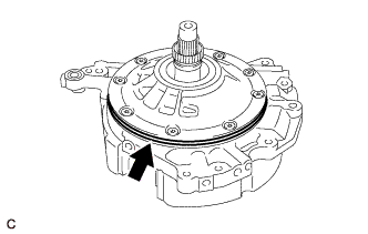
Install the direct multiple disc clutch assembly to the transaxle case sub-assembly.
-
Clean the contact surfaces of the transaxle case sub-assembly and rear transaxle cover sub-assembly.
-
Text in Illustration *a Dimension (A) Place a straightedge on the multiple direct clutch drum and measure the distance between the transaxle case sub-assembly and the straightedge using a vernier caliper (Dimension (A)).
-
Text in Illustration *a Dimension (B) Using a vernier caliper and a straightedge, measure the distance shown in the illustration (Dimension (B)).
-
Calculate the end play value using the following formula:
End play = Dimension (B) - Dimension (A) - Thrust needle roller bearing thickness
End Play 0.007 to 1.113 mm (0.000276 to 0.0438 in.)
-
-
INSTALL REAR TRANSAXLE COVER SUB-ASSEMBLY
-
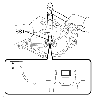
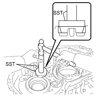
Using SST and a hammer, install a new needle roller bearing to the rear transaxle cover sub-assembly.
- SST
- 09950-60010 ( 09951-00220 )
- 09950-70010 ( 09951-07100 )
Standard Depth 21.5 to 21.9 mm (0.846 to 0.862 in.) -
Text in Illustration *a Adhesive Apply adhesive to the 2 "TORX" screws.
Adhesive Toyota Genuine Adhesive 1324, Three Bond 1324 or equivalent Note
In order to ensure proper sealing of the 2 "TORX" screws, apply adhesive to the 2 "TORX" screws and install them within 10 minutes of adhesive application.
-
Using a T30 "TORX" socket wrench, install the rear transaxle cover plate to the rear transaxle cover sub-assembly with the 2 "TORX" screws.
- Torque:
- 7.5 N*m { 76 kgf*cm, 66 in.*lbf }
-
Text in Illustration *1 Oil Seal Ring Coat 2 new oil seal rings with ATF and install them to the rear transaxle cover sub-assembly.
Note
Confirm that the 2 oil seal rings are correctly located in the grooves of the rear transaxle cover sub-assembly.
-
Text in Illustration *1 Thrust Needle Roller Bearing *2 Thrust Needle Roller Race Coat the thrust needle roller bearing and thrust needle roller race with MP grease and install them to the rear transaxle cover sub-assembly.
Bearing and Race Diameter: mm (in.) - Inside Outside Bearing 48.9 (1.93) 72.0 (2.83) Race 52.2 (2.06) 70.4 (2.77) -
Coat 3 new O-rings with ATF and install them to the transaxle case sub-assembly.
Note
Ensure that the O-rings are not twisted.
-
Clean and degrease the 2 bolts and installation holes in the transaxle case sub-assembly.
-
Remove any remaining seal packing from the contact surfaces of the rear transaxle cover sub-assembly and transaxle case sub-assembly.
Note
Make sure that there is no ATF on the contact surfaces.
-
Text in Illustration *a FIPG Apply FIPG to the transaxle case sub-assembly.
FIPG Toyota Genuine Seal Packing 1281, Three Bond 1281 or equivalent Note
Apply FIPG in a continuous line (width 1.2 mm (0.0472 in.)) along the sealing surface of the transaxle case sub-assembly.
-
Install the rear transaxle cover sub-assembly to the transaxle case sub-assembly with the 12 bolts.
- Torque:
- 23 N*m { 235 kgf*cm, 17 ft.*lbf }
-
Text in Illustration *a Adhesive Apply adhesive to 2 or 3 threads on the ends of the 2 bolts.
Adhesive Toyota Genuine Adhesive 1324, Three Bond 1324 or equivalent Note
In order to ensure proper installation of the 2 bolts, apply adhesive to the 2 bolts and install them within 3 minutes of adhesive application.
-
Install the 2 bolts.
- Torque:
- 17 N*m { 173 kgf*cm, 13 ft.*lbf }
-
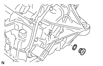
Install a new gasket to the refill plug.
-
Install the refill plug to the rear transaxle cover sub-assembly.
- Torque:
- 49 N*m { 500 kgf*cm, 36 ft.*lbf }
-
Coat 3 new O-rings with ATF and install them to the 3 No. 1 automatic transaxle case plugs.
-
Install the 3 No. 1 automatic transaxle case plugs to the rear transaxle cover sub-assembly.
- Torque:
- 7.4 N*m { 75 kgf*cm, 65 in.*lbf }
-
-
INSPECT INPUT SHAFT SUB-ASSEMBLY END PLAY
-
Using a dial indicator, measure the input shaft sub-assembly end play.
End Play 0.012 to 1.250 mm (0.000473 to 0.0492 in.)
-
-
INSTALL TRANSAXLE CASE GASKET
-
Coat 2 new transaxle case gaskets with ATF and install them to the transaxle case sub-assembly.
-
-
INSTALL TRANSMISSION VALVE BODY ASSEMBLY
-
Coat the O-ring of the transmission wire with ATF.
-
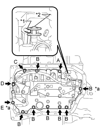
Text in Illustration *1 Manual Valve Lever Shaft Sub-assembly Pin *2 Manual Valve *a Positioning Bolt Insert the manual valve lever shaft sub-assembly pin into the groove on the end of the manual valve as shown in the illustration and temporarily install the transmission valve body assembly to the transaxle case sub-assembly with the 11 bolts.
Note
-
When installing the transmission valve body assembly, be careful not to allow the transmission revolution sensor and transaxle case sub-assembly to interfere with each other.
-
Be sure to insert the manual valve lever shaft sub-assembly pin into the groove on the end of the manual valve.
- Bolt Length Bolt (A) 25 mm (0.984 in.) Bolt (B) 30 mm (1.18 in.) Bolt (C) 35 mm (1.38 in.) Bolt (D) 45 mm (1.77 in.) Bolt (E) 55 mm (2.17 in.) -
-
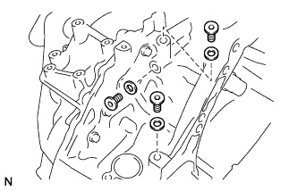
Fully tighten the 2 positioning bolts shown in the illustration.
- Torque:
- 11 N*m { 112 kgf*cm, 8 ft.*lbf }
-
Fully tighten the 9 bolts to install the transmission valve body assembly.
- Torque:
- 11 N*m { 112 kgf*cm, 8 ft.*lbf }
-
-
INSTALL VALVE BODY OIL STRAINER ASSEMBLY
-
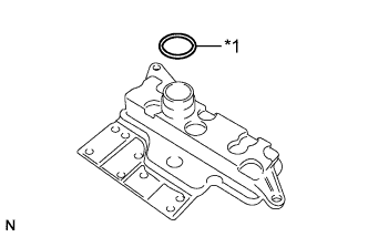
Text in Illustration *1 O-ring Coat a new O-ring with ATF and install it to the valve body oil strainer assembly.
Note
Ensure that the O-ring is not twisted or pinched.
-
Install the valve body oil strainer assembly to the transmission valve body assembly with the 2 bolts.
- Torque:
- 11 N*m { 112 kgf*cm, 8 ft.*lbf }
-
-
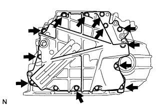
INSTALL AUTOMATIC TRANSAXLE OIL PAN SUB-ASSEMBLY
-
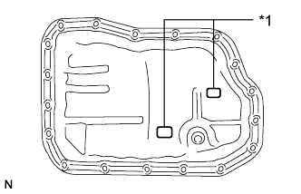
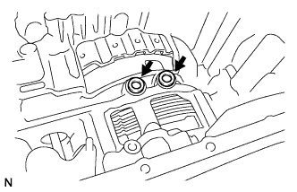
Text in Illustration *1 Transmission Oil Cleaner Magnet Install the 2 transmission oil cleaner magnets to the automatic transaxle oil pan sub-assembly as shown in the illustration.
-
Install a new automatic transaxle oil pan gasket to the automatic transaxle oil pan sub-assembly.
-
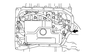
Clean and degrease the bolt and installation hole in the transaxle case sub-assembly.
-
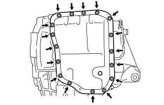
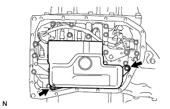
Install the automatic transaxle oil pan sub-assembly with automatic transaxle oil pan gasket to the transaxle case sub-assembly with the 17 bolts.
- Torque:
- 7.5 N*m { 76 kgf*cm, 66 in.*lbf }
Note
Completely remove any oil or grease from the contact surfaces of the transaxle case sub-assembly and automatic transaxle oil pan sub-assembly with automatic transaxle oil pan gasket before installation.
-
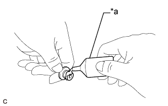
Text in Illustration *a Adhesive Apply adhesive to the bolt.
Adhesive Toyota Genuine Adhesive 1344, Three Bond 1344 or equivalent Note
In order to ensure proper installation of the bolt, apply adhesive to the bolt and install it within 3 minutes of adhesive application.
-
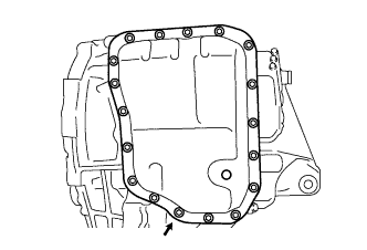
Install the bolt.
- Torque:
- 7.0 N*m { 71 kgf*cm, 62 in.*lbf }
-
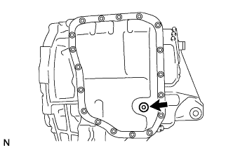
Using a 6 mm hexagon socket wrench, install the No. 1 transmission oil filler tube to the automatic transaxle oil pan sub-assembly.
- Torque:
- 1.7 N*m { 17 kgf*cm, 15 in.*lbf }
-
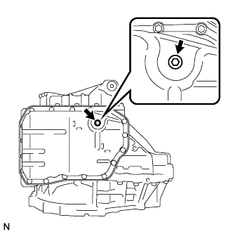
Using a 6 mm hexagon socket wrench, install the overflow plug and a new gasket to the automatic transaxle oil pan sub-assembly.
- Torque:
- 40 N*m { 408 kgf*cm, 30 ft.*lbf }
-
-
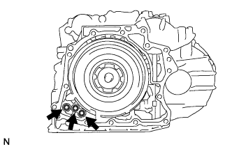
INSTALL NO. 2 TRANSAXLE CASE PLUG
-
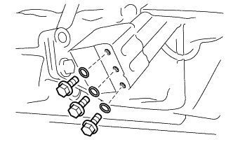
Clean and degrease the 3 No. 2 transaxle case plugs and installation holes in the transaxle housing.
-
Install 3 new gaskets to the 3 No. 2 transaxle case plugs.
-
Text in Illustration *a Adhesive Apply adhesive to the 3 No. 2 transaxle case plugs.
Adhesive Toyota Genuine Adhesive 1324, Three Bond 1324 or equivalent Note
In order to ensure proper installation of the 3 No. 2 transaxle case plugs, apply adhesive to the 3 No. 2 transaxle case plugs and install them within 3 minutes of adhesive application.
-
Using a 6 mm hexagon socket wrench, install the 3 No. 2 transaxle case plugs to the transaxle housing.
- Torque:
- 17 N*m { 173 kgf*cm, 13 ft.*lbf }
-
-
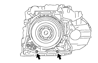
INSTALL NO. 1 TRANSAXLE CASE PLUG
-
Coat 3 new O-rings with ATF and install them to the 3 No. 1 transaxle case plugs.
-
Install the 3 No. 1 transaxle case plugs to the transaxle case sub-assembly.
- Torque:
- 7.4 N*m { 75 kgf*cm, 65 in.*lbf }
-
-
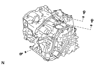
INSTALL OIL COOLER TUBE UNION (INLET OIL COOLER UNION)
-
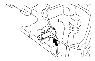
Coat a new O-ring with ATF and install it to the oil cooler tube union (inlet oil cooler union).
-
Install the oil cooler tube union (inlet oil cooler union) to the transaxle case sub-assembly.
- Torque:
- 27 N*m { 275 kgf*cm, 20 ft.*lbf }
-
-
INSTALL OIL COOLER TUBE UNION (OUTLET OIL COOLER UNION)
-
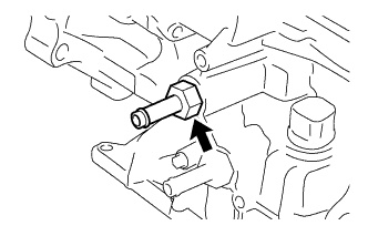
Coat a new O-ring with ATF and install it to the oil cooler tube union (outlet oil cooler union).
-
Install the oil cooler tube union (outlet oil cooler union) to the transaxle case sub-assembly.
- Torque:
- 27 N*m { 275 kgf*cm, 20 ft.*lbf }
-
-
INSTALL PARK/NEUTRAL POSITION SWITCH ASSEMBLY
-
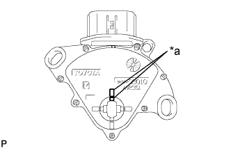
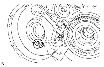
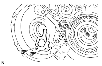
Text in Illustration *a Protrusion Align the protrusions of the park/neutral position switch assembly as shown in the illustration.
-
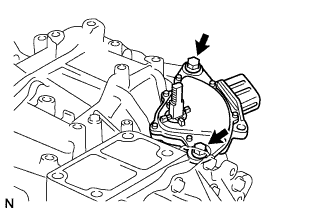
Install the park/neutral position switch assembly to the transaxle case sub-assembly with the 2 bolts.
- Torque:
- 5.4 N*m { 55 kgf*cm, 48 in.*lbf }
Note
-
Before installing the park/neutral position switch assembly, remove any dirt or rust on the manual valve lever shaft sub-assembly. Be sure to install the park/neutral position switch assembly straight along the manual valve lever shaft sub-assembly while being careful not to deform the plate spring that supports the manual valve lever shaft sub-assembly. If the plate spring is deformed, the park/neutral position switch assembly cannot be reinstalled correctly.
-
After installing the park/neutral position switch assembly, confirm that the 2 protrusions on the park/neutral position switch assembly are aligned.
-
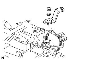
Install the transmission control shaft lever to the manual valve lever shaft sub-assembly with the washer and nut.
- Torque:
- 13 N*m { 130 kgf*cm, 9 ft.*lbf }
-
-
INSTALL BREATHER PLUG HOSE
-
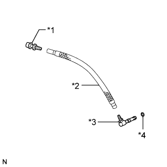
Text in Illustration *1 No. 1 Breather Plug (ATM) *2 Breather Plug Hose *3 No. 2 Breather Plug (ATM) *4 O-ring Coat a new O-ring with ATF and install it to the No. 2 breather plug (ATM).
-
Install the No. 1 breather plug (ATM) and No. 2 breather plug (ATM) to the breather plug hose.
-
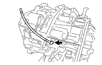
Install the breather plug hose to the transaxle case sub-assembly.
-