TRANSMISSION CONTROL CABLE INSTALLATION
-
INSTALL TRANSMISSION CONTROL CABLE ASSEMBLY
Note
Before installing the transmission control cable assembly, check that the park/neutral position switch assembly and the shift lever are in neutral.
-
Pass the transmission control cable assembly from the cabin to the engine compartment.
-
Install the transmission control cable assembly with the 2 bolts.
- Torque:
- 5.0 N*m { 51 kgf*cm, 44 in.*lbf }
-
Install the dash panel insulator to the original position.
-
Connect the transmission control cable assembly to the transmission control cable bracket with a new clip.
-
Connect the transmission control cable assembly to the control shaft lever with the nut.
- Torque:
- 13 N*m { 131 kgf*cm, 9 ft.*lbf }
Note
Before connecting the transmission control cable assembly, check that the park/neutral position switch assembly and the shift lever are in neutral.
-
Connect the wire harness clamp.
-
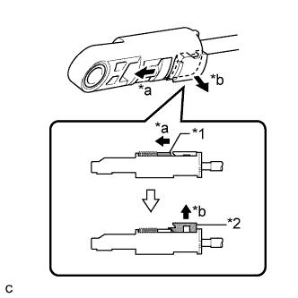
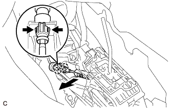
Text in Illustration *1 Slider *2 Lock Piece *a Slide *b Pull Slide the slider of the transmission control cable assembly as shown in the illustration and pull the lock piece outward.
-
Engage the 2 claws to connect the transmission control cable assembly to the lower shift lever assembly.
-
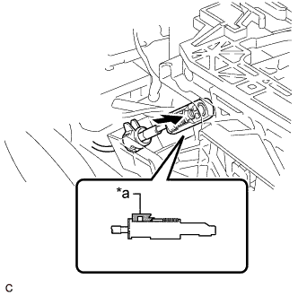
Text in Illustration *a Lock Piece Connect the end of the transmission control cable assembly to the lower shift lever assembly.
Note
-
Check that the lock piece is pulled out.
-
Push the end of the transmission control cable assembly all the way to the base of the lower shift lever assembly pin.
-
-
Push the lock piece into the adjuster case.
Note
-
Check that the park/neutral position switch assembly and the shift lever are in neutral.
-
Securely push in the lock piece until the slider lock is engaged.
-
-
-
CONNECT NO. 1 PARKING BRAKE CABLE ASSEMBLY
-
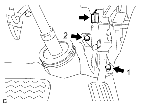
Install the No. 1 parking brake cable assembly with the bolt and nut.
- Torque:
- Bolt
- 15 N*m { 153 kgf*cm, 11 ft.*lbf }
- Nut
- 5.4 N*m { 55 kgf*cm, 48 in.*lbf }
-
Install the floor carpet to the original position.
-
-
INSTALL ACCELERATOR PEDAL SENSOR ASSEMBLY
Note
-
Avoid physical shock to the accelerator pedal sensor assembly.
-
Do not disassemble the accelerator pedal sensor assembly.
-
The accelerator pedal sensor assembly does not require lubrication.
-
Do not apply oil or other lubricants to the accelerator pedal sensor assembly. If applied, the accelerator pedal sensor assembly must be replaced.
-
Temporarily install the accelerator pedal sensor assembly with the 2 bolts.
-
Tighten the 2 bolts in the order shown in the illustration.
- Torque:
- 5.4 N*m { 55 kgf*cm, 48 in.*lbf }
-
Connect the accelerator pedal sensor assembly connector.
-
-
INSTALL AIRBAG SENSOR ASSEMBLY
-
INSTALL AIR CLEANER CASE SUB-ASSEMBLY
-
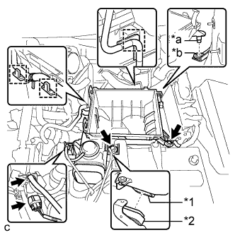
Text in Illustration *1 Air Cleaner Case Sub-assembly *2 Inlet No. 1 Air Cleaner *a Projection *b Hole Install the air cleaner case sub-assembly to the inlet No. 1 air cleaner.
-
Insert the projection of the air cleaner case sub-assembly to the hole of the No. 2 air cleaner bracket as shown in the illustration.
-
Tighten the 2 bolts.
- Torque:
- 5.0 N*m { 51 kgf*cm, 44 in.*lbf }
-
Connect the wire harness clamp, connector, vacuum hose and No. 1 fuel vapor feed hose.
-
-
INSTALL AIR CLEANER FILTER ELEMENT SUB-ASSEMBLY
-
INSTALL AIR CLEANER CAP SUB-ASSEMBLY
-
Connect the air cleaner cap sub-assembly to the throttle with motor body assembly with the hose clamp.
-
Install the air cleaner cap with hose to the air cleaner case with the 2 clamps.
-
Connect the wire harness clamp and mass air flow meter connector.
-
Connect the 3 hoses.
-
Connect the ventilation hose.
-
Connect the mass air flow meter connector and wire harness clamp.
-
-
INSTALL INLET NO. 2 AIR CLEANER
-
Install the inlet No. 2 air cleaner to the air cleaner case sub-assembly with the 2 bolts.
- Torque:
- 8.0 N*m { 82 kgf*cm, 71 in.*lbf }
-
Connect the 2 wire harness clamps and vacuum hose clamp.
-
-
INSTALL COOL AIR INTAKE DUCT SEAL
-
INSPECT SHIFT LEVER POSITION
-
When the shift lever is moved from P to R with the engine switch on (IG) and brake pedal depressed, make sure that the shift lever moves smoothly and correctly the position.
-
Start the engine and make sure that the vehicle moves forward when the shift lever is moved from N to D and moves rearward when the shift lever is moved to R.
-
-
ADJUST SHIFT LEVER POSITION
-
Move the shift lever to N.
-
Remove the console box Click here.
-
Disconnect the end of the transmission control cable assembly from the lower shift lever assembly
-
Disengage the 2 claws and disconnect the transmission control cable assembly from the lower shift lever assembly.
-
Text in Illustration *1 Slider *2 Lock Piece *a Slide *b Pull Slide the slider of the transmission control cable assembly as shown in the illustration and pull the lock piece outward.
-
Engage the 2 claws to connect the transmission control cable assembly to the lower shift lever assembly.
-
Text in Illustration *a Lock Piece Connect the end of the transmission control cable assembly to the lower shift lever assembly.
Note
-
Check that the lock piece is pulled out.
-
Push the end of the transmission control cable assembly all the way to the base of the lower shift lever assembly pin.
-
-
Push the lock piece into the adjuster case.
Note
-
Check that the park/neutral position switch assembly and the shift lever are in neutral.
-
Securely push in the lock piece until the slider lock is engaged.
-
-
After adjusting the shift lever position, check the operation and function of the shift lever. If there is a problem, adjust the position again.
-
Install the console box Click here.
-