AUTOMATIC TRANSAXLE SYSTEM, Diagnostic DTC:P0989, P0990
| DTC Code | DTC Name |
|---|---|
| P0989 | Transmission Fluid Pressure Sensor / Switch "E" Circuit Low |
| P0990 | Transmission Fluid Pressure Sensor / Switch "E" Circuit High |
DESCRIPTION
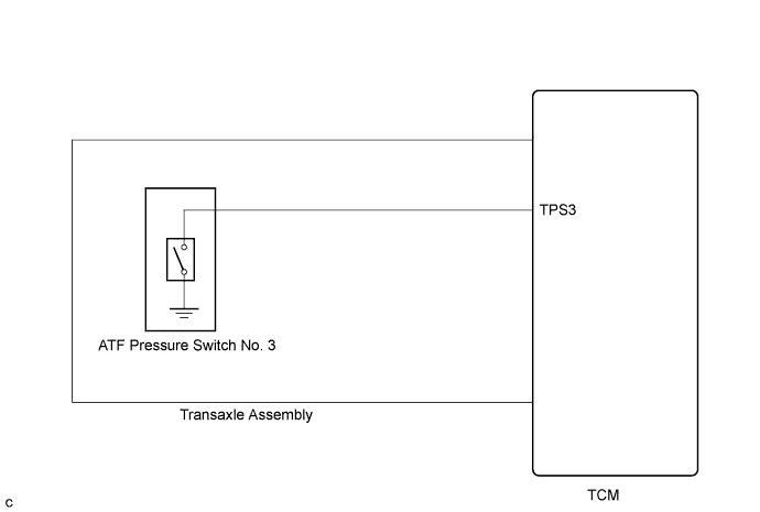
ATF pressure switch No. 3 is installed in the lock-up solenoid ATF output passage and is used to detect a malfunction in the lock-up solenoid.
| DTC No. | DTC Detection Condition | Trouble Area |
|---|---|---|
| P0989 | Transmission fluid pressure switch No. 3 is OFF when lock-up occurs in response to a lock-up request (2 trip detection logic). |
|
| P0990 | When both of the following are detected (2 trip detection logic):
|
MONITOR DESCRIPTION
The TCM illuminates the MIL and stores the DTC when the TCM detects that the ATF pressure switch is OFF with the lock-up solenoid ON or when the TCM detects that the ATF pressure switch is ON with the lock-up solenoid OFF.
WIRING DIAGRAM
INSPECTION PROCEDURE
PROCEDURE
-
CHECK OTHER DTC OUTPUT (IN ADDITION TO DTC P0989 OR P0990)
-
Connect the intelligent tester to the DLC3.
-
Turn the engine switch on (IG).
-
Turn the intelligent tester on.
-
Enter the following menus: Powertrain / ECT / DTC.
-
Read the DTCs using the intelligent tester.
Result Display (DTC Output) Proceed to Only "P0990" is output A Only "P0989" is output B "P0989 or P0990" and other DTCs are output C Tech Tips
If a solenoid is stuck OFF, DTCs for several solenoids including the malfunctioning solenoid will be detected.
B 
CHECK TRANSMISSION WIRE Click here
C 
GO TO DTC CHART Click here
A 
-
-
CHECK TRANSMISSION WIRE (SHORT TO GROUND)
-
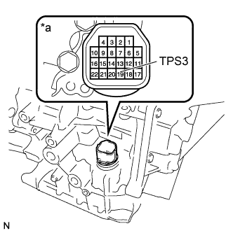
Text in Illustration *a Component without harness connected
(Transmission Wire)
Remove the TCM.
-
Measure the resistance according to the value(s) in the table below.
Standard Resistance Tester Condition Condition Specified Condition 19 (TPS3) - Body ground (Valve body assembly) and other terminals Always 10 kΩ or higher
NG
CHECK ATF TEMPERATURE SENSOR ASSEMBLY (ATF PRESSURE SWITCH NO. 3) Click here
OK 
REPLACE TCM Click here
-
-
CHECK ATF TEMPERATURE SENSOR ASSEMBLY (ATF PRESSURE SWITCH NO. 3)
-
Remove the oil strainer assembly.
-
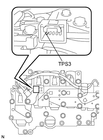
Disconnect the connector from the ATF temperature sensor assembly.
-
Measure the resistance according to the value(s) in the table below.
Standard Resistance Tester Condition Condition Specified Condition 1 (TPS3) - Body ground (Valve body assembly) and other terminals Always 10 kΩ or higher
NG
REPLACE ATF TEMPERATURE SENSOR ASSEMBLY Click here
OK
REPLACE TRANSMISSION WIRE Click here
-
-
CHECK TRANSMISSION WIRE
-
Remove the oil strainer assembly.
-
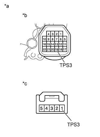
Text in Illustration *a Component without harness connected
(Transmission Wire)
*b TCM Side *c ATF Temperature Sensor Side Remove the TCM.
-
Disconnect the connector from the ATF temperature sensor assembly.
-
Measure the resistance according to the value(s) in the table below.
Standard Resistance Tester Condition Condition Specified Condition 19 (TPS3) TCM side - 1 (TPS3) sensor side Always Below 1 Ω 1 (TPS3) sensor side - Body ground (Valve body assembly) and other terminals Always 10 kΩ or higher
NG
REPLACE TRANSMISSION WIRE Click here
OK
-
-
REPLACE ATF TEMPERATURE SENSOR ASSEMBLY
NEXT
-
CHECK IF DTC OUTPUT RECURS
-
Connect the intelligent tester to the DLC3.
-
Start the engine and turn the intelligent tester on.
-
Clear the DTCs Click here.
Tech Tips
Write down the currently output DTCs before clearing them.
-
Perform the monitor drive pattern Click here.
-
Enter the following menus: Powertrain / ECT / DTC.
-
Read the DTCs using the intelligent tester.
Result Display (DTC Output) Proceed to Only "P0989" is output A No output B
B
END
A
REPLACE TCM Click here
-