CRUISE CONTROL SYSTEM Cruise Control Switch Circuit
DESCRIPTION
The cruise control switch is used to turn the cruise control system on and off, as well as operate 7 functions: SET, - (COAST), TAP-DOWN, RES (RESUME), + (ACCEL), TAP-UP and CANCEL. The SET, TAP-DOWN and - (COAST) functions, and the RES (RESUME), TAP-UP and + (ACCEL) functions are operated with the same switch. The cruise control switch is an automatic return type switch which turns on only while operating it in the direction of each arrow and turns off after releasing it. The internal contact points of the cruise control switch turn on with switch operation. Then the ECM reads the voltage value that has been changed by the switch operation to control SET, - (COAST), RES (RESUME), + (ACCEL), and CANCEL.
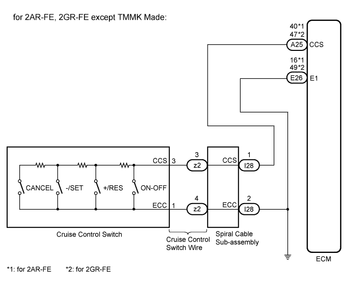
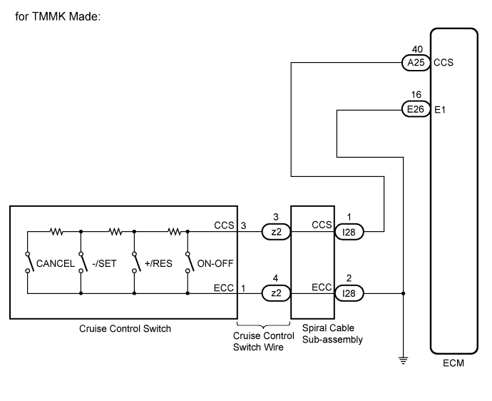
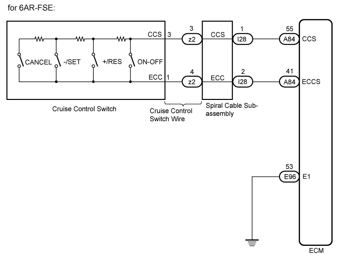
WIRING DIAGRAM
INSPECTION PROCEDURE
PROCEDURE
-
READ VALUE ON GTS
-
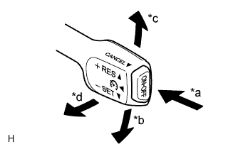
Text in Illustration *a ON-OFF *b -/SET *c +/RES *d CANCEL Connect the GTS to the DLC3.
-
Turn the ignition switch to ON.
-
Turn the GTS on.
-
Select the following menu items: Powertrain / Cruise Control / Data List.
-
for 2AR-FE, 2GR-FE:
Check the Data List to confirm proper functioning of the cruise control switch.
Cruise Control Tester Display Measurement Item/Range Normal Condition Diagnostic Note Main SW M-CPU Cruise control switch signal (Main CPU) / ON or OFF ON: Cruise control switch (ON-OFF button) pushed
OFF: Cruise control switch (ON-OFF button) released
- Cancel Switch CANCEL switch signal / ON or OFF ON: CANCEL switch on
OFF: CANCEL switch off
- SET/COAST Switch -/SET switch signal / ON or OFF ON: -/SET switch on
OFF: -/SET switch off
- RES/ACC Switch +/RES switch signal / ON or OFF ON: +/RES switch on
OFF: +/RES switch off
- OK When the cruise control switch is operated, the display changes as shown above. -
for 6AR-FSE:
Check the Data List to confirm proper functioning of the cruise control switch.
Cruise Control Tester Display Measurement Item/Range Normal Condition Diagnostic Note Cancel Switch CANCEL switch signal / ON or OFF ON: CANCEL switch on
OFF: CANCEL switch off
- -SET Switch -/SET switch signal / ON or OFF ON: -/SET switch on
OFF: -/SET switch off
- +RES Switch +/RES switch signal / ON or OFF ON: +/RES switch on
OFF: +/RES switch off
- Cruise Ready Main-CPU Cruise control system standby condition (Main-CPU) / ON or OFF ON: Cruise control main switch (Main- CPU) SET
OFF: Cruise control main switch (Main- CPU) UNSET
- OK When the cruise control switch is operated, the display changes as shown above.
NG 
INSPECT CRUISE CONTROL SWITCH Click here
OK 
PROCEED TO NEXT SUSPECTED AREA SHOWN IN PROBLEM SYMPTOMS TABLE Click here
-
-
INSPECT CRUISE CONTROL SWITCH
-
Remove the cruise control switch Click here.
-
Measure the resistance according to the value(s) in the table below.
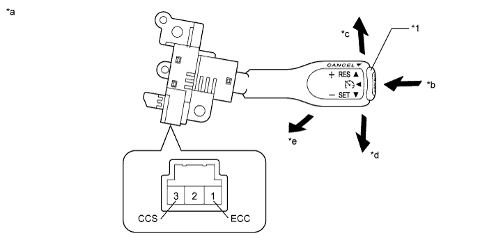
Standard Resistance Tester Connection Condition Specified Condition 1 - 3 Cruise control switch (ON-OFF button) released 10 kΩ or higher Cruise control switch (ON-OFF button) pushed Below 2.5 Ω +/RES 235 to 245 Ω -/SET 617 to 643 Ω CANCEL 1509 to 1571 Ω Text in Illustration *1 Cruise Control Switch (ON-OFF button) - - *a Component without harness connected
(Cruise Control Switch)
*b ON-OFF *c +/RES *d -/SET *e CANCEL - -
NG 
REPLACE CRUISE CONTROL SWITCH Click here
OK 
-
-
CHECK CRUISE CONTROL SWITCH WIRE
-
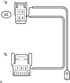
Text in Illustration *a Front view of wire harness connector
(to Spiral Cable Sub-assembly)
*b Front view of wire harness connector
(to Cruise Control Switch)
Disconnect the spiral cable sub-assembly connector.
-
Measure the resistance according to the value(s) in the table below.
Standard Resistance (Check for Open) Tester Connection Condition Specified Condition Cruise control switch side connector terminal 3 - z2-3 Always Below 1 Ω Cruise control switch side connector terminal 1 - z2-4 Always Below 1 Ω
NG
REPAIR OR REPLACE CRUISE CONTROL SWITCH WIRE
OK
-
-
CHECK SPIRAL CABLE SUB-ASSEMBLY
Note
The spiral cable sub-assembly is an important part of the SRS airbag system. Incorrect removal or installation of the spiral cable sub-assembly may prevent the airbag from deploying. Be sure to read the pages shown in the brackets.
-
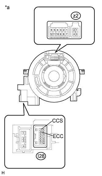
Text in Illustration *a Component without harness connected
(Spiral Cable Sub-assembly)
Remove the spiral cable sub-assembly.
-
Measure the resistance according to the value(s) in the table below.
Standard Resistance (Check for Open) Tester Connection Condition Specified Condition z2-3 - I28-1 (CCS) Center Below 3 Ω 2.5 rotations to the left 2.5 rotations to the right z2-4 - I28-2 (ECC) Center Below 3 Ω 2.5 rotations to the left 2.5 rotations to the right -
After setting the spiral cable sub-assembly to the center position, rotate the spiral cable sub-assembly 2.5 times clockwise. Then while rotating the spiral cable sub-assembly 5 times counterclockwise, measure the resistance according to the value(s) in the table below.
Standard Resistance (Check for Open) Tester Connection Condition Specified Condition z2-3 - I28-1 (CCS) Always Below 3 Ω z2-4 - I28-2 (ECC) Always Below 3 Ω Tech Tips
The spiral cable sub-assembly makes a maximum of approximately 5 rotations.
NG
REPLACE SPIRAL CABLE SUB-ASSEMBLY Click here
OK
-
-
CHECK HARNESS AND CONNECTOR (SPIRAL CABLE SUB-ASSEMBLY - ECM AND BODY GROUND)
-
Disconnect the ECM connector.
-
Disconnect the spiral cable sub-assembly connector.
-
Measure the resistance according to the value(s) in the table below.
Standard Resistance (Check for Open) for 2AR-FE Tester Connection Condition Specified Condition A25-40 (CCS) - I28-1 (CCS) Always Below 1 Ω for 2GR-FE Tester Connection Condition Specified Condition A25-47 (CCS) - I28-1 (CCS) Always Below 1 Ω for 6AR-FSE Tester Connection Condition Specified Condition A84-55 (CCS) - I28-1 (CCS) Always Below 1 Ω A84-41 (ECCS) - I28-2 (ECC) Always Below 1 Ω Standard Resistance (Check for Short) for 2AR-FE Tester Connection Condition Specified Condition A25-40 (CCS) or I28-1 (CCS) - Body ground Always 10 kΩ or higher for 2GR-FE Tester Connection Condition Specified Condition A25-47 (CCS) or I28-1 (CCS) - Body ground Always 10 kΩ or higher for 6AR-FSE Tester Connection Condition Specified Condition A84-55 (CCS) or I28-1 (CCS) - Body ground Always 10 kΩ or higher A84-41 (ECCS) or I28-2 (ECC) - Body ground Always 10 kΩ or higher Result Result Proceed to OK (for 2AR-FE, 2GR-FE) A OK (for 6AR-FSE) B NG C -
Reconnect the spiral cable sub-assembly connector.
-
Reconnect the ECM connector.
B
CHECK HARNESS AND CONNECTOR (ECM - BODY GROUND) Click here
C
REPAIR OR REPLACE HARNESS OR CONNECTOR (SPIRAL CABLE SUB-ASSEMBLY - ECM)
A
-
-
CHECK HARNESS AND CONNECTOR (SPIRAL CABLE SUB-ASSEMBLY - BODY GROUND)
-
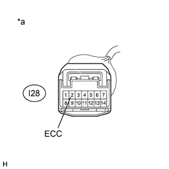
Text in Illustration *a Front view of wire harness connector
(to Spiral Cable Sub-assembly)
Disconnect the spiral cable sub-assembly connector.
-
Measure the resistance according to the value(s) in the table below.
Standard Resistance (Check for Open) Tester Connection Condition Specified Condition I28-2 (ECC) - Body ground Always Below 1 Ω Result Result Proceed to OK (for 2AR-FE) A OK (for 2GR-FE) B NG C -
Reconnect the spiral cable sub-assembly connector.
B
REPLACE ECM Click here
C
REPAIR OR REPLACE HARNESS OR CONNECTOR (SPIRAL CABLE SUB-ASSEMBLY - BODY GROUND)
A
REPLACE ECM Click here
-
-
CHECK HARNESS AND CONNECTOR (ECM - BODY GROUND)
-
Disconnect the ECM connector.
-
Measure the resistance according to the value(s) in the table below.
Standard Resistance (Check for Open) Tester Connection Condition Specified Condition E96-53 (E1) - Body ground Always Below 1 Ω
NG
REPAIR OR REPLACE HARNESS OR CONNECTOR (ECM - BODY GROUND)
OK
REPLACE ECM Click here
-