CRUISE CONTROL SYSTEM TERMINALS OF ECM
-
CHECK ECM
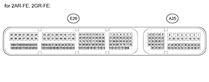
for 2AR-FE except TMMK Made: Terminal No. (Symbols) Wiring Color Terminal Description Condition Specified Condition A25-23 (TC) - E26-16 (E1) P - BR Connected to terminal TC of DLC3 Ignition switch ON 11 to 14 V A25-23 (TC) - E26-16 (E1) P - BR Connected to terminal TC of DLC3 Terminals TC and CG of DLC3 connected Below 1 V A25-11 (STP) - E26-16 (E1) BE - BR Stop light signal Ignition switch ON, Brake pedal depressed 11 to 14 V A25-11 (STP) - E26-16 (E1) BE - BR Stop light signal Ignition switch ON, Brake pedal released Below 1 V A25-40 (CCS) - E26-16 (E1) W - BR Cruise control switch circuit Cruise control switch OFF 10 kΩ or higher A25-40 (CCS) - E26-16 (E1) W - BR Cruise control switch circuit Cruise control switch ON Below 2.5 Ω A25-40 (CCS) - E26-16 (E1) W - BR Cruise control switch circuit +/RES switch ON 235 to 245 Ω A25-40 (CCS) - E26-16 (E1) W - BR Cruise control switch circuit -/SET switch ON 617 to 643 Ω A25-40 (CCS) - E26-16 (E1) W - BR Cruise control switch circuit CANCEL switch ON 1509 to 1571 Ω A25-24 (ST1-) - E26-16 (E1) GR - BR Stop light signal Ignition switch ON, Brake pedal depressed Below 1 V A25-24 (ST1-) - E26-16 (E1) GR - BR Stop light signal Ignition switch ON,
Brake pedal released
11 to 14 V E26-67 (D) - E26-16 (E1) G - BR D shift position signal Ignition switch ON,
Shift lever D or S position
11 to 14 V E26-67 (D) - E26-16 (E1) G - BR D shift position signal Ignition switch ON,
Shift lever except D or S position
Below 1 V A25-43 (SFTD) - E26-16 (E1) V - BR Down shift switch signal Ignition switch ON and shift lever S position 11 to 14 V Ignition switch ON and shift lever "-" position (Down shift) Below 1 V A25-42 (SFTU) - E26-16 (E1) R - BR Up shift switch signal Ignition switch ON and shift lever S position 11 to 14 V Ignition switch ON and shift lever "+" position (Up shift) Below 1 V for TMMK Made 2AR-FE: Terminal No. (Symbols) Wiring Color Terminal Description Condition Specified Condition A25-23 (TC) - E26-16 (E1) P - BR Connected to terminal TC of DLC3 Ignition switch ON 11 to 14 V A25-23 (TC) - E26-16 (E1) P - BR Connected to terminal TC of DLC3 Terminals TC and CG of DLC3 connected Below 1 V A25-11 (STP) - E26-16 (E1) BE - BR Stop light signal Ignition switch ON, Brake pedal depressed 11 to 14 V A25-11 (STP) - E26-16 (E1) BE - BR Stop light signal Ignition switch ON, Brake pedal released Below 1 V A25-40 (CCS) - E26-16 (E1) W - BR Cruise control switch circuit Cruise control switch OFF 10 kΩ or higher A25-40 (CCS) - E26-16 (E1) W - BR Cruise control switch circuit Cruise control switch ON Below 2.5 Ω A25-40 (CCS) - E26-16 (E1) W - BR Cruise control switch circuit +/RES switch ON 235 to 245 Ω A25-40 (CCS) - E26-16 (E1) W - BR Cruise control switch circuit -/SET switch ON 617 to 643 Ω A25-40 (CCS) - E26-16 (E1) W - BR Cruise control switch circuit CANCEL switch ON 1509 to 1571 Ω A25-24 (ST1-) - E26-16 (E1) GR - BR Stop light signal Ignition switch ON, Brake pedal depressed Below 1 V A25-24 (ST1-) - E26-16 (E1) GR - BR Stop light signal Ignition switch ON,
Brake pedal released
11 to 14 V E26-57 (D) - E26-16 (E1) G - BR D shift position signal Ignition switch ON,
Shift lever D or S position
11 to 14 V E26-57 (D) - E26-16 (E1) G - BR D shift position signal Ignition switch ON,
Shift lever except D or S position
Below 1 V A25-43 (SFTD) - E26-16 (E1) V - BR Down shift switch signal Ignition switch ON and shift lever S position 11 to 14 V Ignition switch ON and shift lever "-" position (Down shift) Below 1 V A25-42 (SFTU) - E26-16 (E1) R - BR Up shift switch signal Ignition switch ON and shift lever S position 11 to 14 V Ignition switch ON and shift lever "+" position (Up shift) Below 1 V for 2GR-FE: Terminal No. (Symbols) Wiring Color Terminal Description Condition Specified Condition A25-45 (TC) - E26-49 (E1) P - BR Connected to terminal TC of DLC3 Ignition switch ON 11 to 14 V A25-45 (TC) - E26-49 (E1) P - BR Connected to terminal TC of DLC3 Terminals TC and CG of DLC3 connected Below 1 V A25-51 (STP) - E26-49 (E1) BE - BR Stop light signal Ignition switch ON, Brake pedal depressed 11 to 14 V A25-51 (STP) - E26-49 (E1) BE - BR Stop light signal Ignition switch ON, Brake pedal released Below 1 V A25-47 (CCS) - E26-49 (E1) W - BR Cruise control switch circuit Cruise control switch OFF 10 kΩ or higher A25-47 (CCS) - E26-49 (E1) W - BR Cruise control switch circuit Cruise control switch ON Below 2.5 Ω A25-47 (CCS) - E26-49 (E1) W - BR Cruise control switch circuit +/RES switch ON 235 to 245 Ω A25-47 (CCS) - E26-49 (E1) W - BR Cruise control switch circuit -/SET switch ON 617 to 643 Ω A25-47 (CCS) - E26-49 (E1) W - BR Cruise control switch circuit CANCEL switch ON 1509 to 1571 Ω A25-36 (ST1-) - E26-49 (E1) GR - BR Stop light signal Ignition switch ON, Brake pedal depressed Below 1 V A25-36 (ST1-) - E26-49 (E1) GR - BR Stop light signal Ignition switch ON,
Brake pedal released
11 to 14 V E26-69 (D) - E26-49 (E1) G - BR D shift position signal Ignition switch ON,
Shift lever D or S position
11 to 14 V E26-69 (D) - E26-49 (E1) G - BR D shift position signal Ignition switch ON,
Shift lever except D or S position
Below 1 V A25-50 (SFTD) - E26-49 (E1) V - BR Down shift switch signal Ignition switch ON and shift lever S position 11 to 14 V Ignition switch ON and shift lever "-" position (Down shift) Below 1 V A25-34 (SFTU) - E26-49 (E1) R - BR Up shift switch signal Ignition switch ON and shift lever S position 11 to 14 V Ignition switch ON and shift lever "+" position (Up shift) Below 1 V 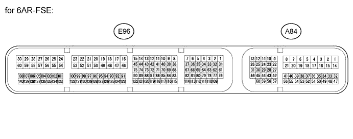
for 6AR-FSE: Terminal No. (Symbols) Wiring Color Terminal Description Condition Specified Condition A84-33 (TC) - E96-53 (E1) P - W-B Connected to terminal TC of DLC3 Ignition switch ON 11 to 14 V A84-33 (TC) - E96-53 (E1) P - W-B Connected to terminal TC of DLC3 Terminals TC and CG of DLC3 connected Below 1 V A84-9 (STP) - E96-53 (E1) BE - W-B Stop light signal Ignition switch ON, Brake pedal depressed 11 to 14 V A84-9 (STP) - E96-53 (E1) BE - W-B Stop light signal Ignition switch ON, Brake pedal released Below 1 V A84-55 (CCS) - A84-41 (ECCS) W - W-B Cruise control switch circuit Cruise control switch OFF 10 kΩ or higher A84-55 (CCS) - A84-41 (ECCS) W - W-B Cruise control switch circuit Cruise control switch ON Below 2.5 Ω A84-55 (CCS) - A84-41 (ECCS) W - W-B Cruise control switch circuit +/RES switch ON 235 to 245 Ω A84-55 (CCS) - A84-41 (ECCS) W - W-B Cruise control switch circuit -/SET switch ON 617 to 643 Ω A84-55 (CCS) - A84-41 (ECCS) W - W-B Cruise control switch circuit CANCEL switch ON 1509 to 1571 Ω A84-10 (ST1-) - E96-53 (E1) GR - W-B Stop light signal Ignition switch ON, Brake pedal depressed Below 1 V A84-10 (ST1-) - E96-53 (E1) GR - W-B Stop light signal Ignition switch ON,
Brake pedal released
11 to 14 V E96-34 (D) - E96-53 (E1) G - W-B D shift position signal Ignition switch ON,
Shift lever D or S position
11 to 14 V E96-34 (D) - E96-53 (E1) G - W-B D shift position signal Ignition switch ON,
Shift lever except D or S position
Below 1 V A84-43 (SFTD) - E96-53 (E1) V - W-B Down shift switch signal Ignition switch ON and shift lever S position 11 to 14 V Ignition switch ON and shift lever "-" position (Down shift) Below 1 V A84-42 (SFTU) - E96-53 (E1) R - W-B Up shift switch signal Ignition switch ON and shift lever S position 11 to 14 V Ignition switch ON and shift lever "+" position (Up shift) Below 1 V