STARTER (for 1.6 kW Type) REASSEMBLY
-
INSTALL PLANETARY GEAR
-
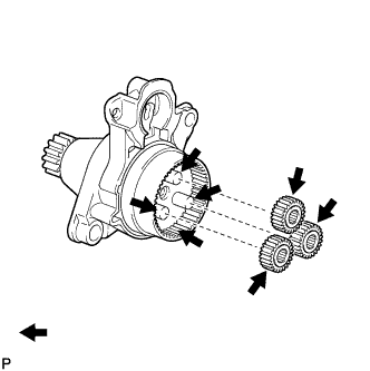
Apply high-temperature grease to the planetary gears and pin parts of the planetary shaft.
Text in Illustration 
High-temperature grease -
Install the 3 planetary gears.
-
-
INSTALL RUBBER SEAL
-
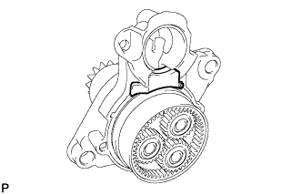
Install the rubber seal to the repair service starter kit.
-
-
INSTALL STARTER ARMATURE ASSEMBLY
-
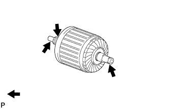
Apply high-temperature grease to the washer and the armature shaft.
Text in Illustration High-temperature grease -
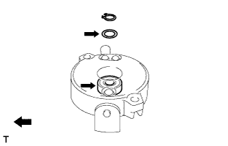
Apply high-temperature grease to the plate washer and bearing, as shown in the illustration.
Text in Illustration High-temperature grease -
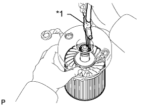
Text in Illustration *1 Snap Ring Pliers Install the starter armature assembly to the starter commutator end frame assembly.
-
Install the washer.
-
Using snap ring pliers, securely install a new snap ring to the armature shaft groove.
Note
Be sure to install the snap ring, properly because it easily expands.
-
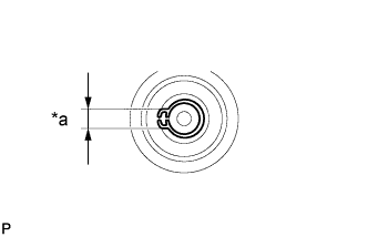
Text in Illustration *a Length Using a vernier caliper, measure the length of the snap ring.
Maximum length 5.0 mm (0.197 in.) If the length is more than the maximum, replace the snap ring with a new one.
-
-
INSTALL STARTER COMMUTATOR END FRAME COVER
-
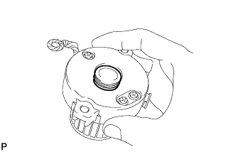
Install the starter commutator end frame cover to the starter commutator end frame assembly.
-
-
INSTALL STARTER ARMATURE PLATE
-
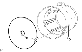
Text in Illustration *a Keyway *b Key Insert the armature plate into the starter yoke assembly.
-
Align the keyway of the starter armature plate with the key inside the starter yoke, and install the starter armature plate.
-
-
INSTALL STARTER COMMUTATOR END FRAME ASSEMBLY
-
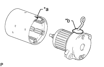
Text in Illustration *a Cutout *b Rubber Align the rubber of the end frame with the cutout of the starter yoke assembly.
-
Install the starter commutator end frame assembly to the starter yoke assembly.
Note
The magnet of the starter yoke assembly may attract the starter armature when the starter commutator end assembly frame is installed, causing the magnet to break.
-
-
INSTALL STARTER YOKE ASSEMBLY
-
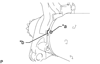
Text in Illustration *a Protrusion *b Cutout Align the protrusion of the starter yoke assembly with the cutout of the repair service starter kit.
-
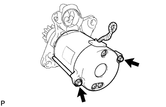
Install the starter yoke assembly with the 2 through-bolts.
- Torque:
- 6.0 N*m { 61 kgf*cm, 53 in.*lbf }
-
-
INSTALL MAGNET STARTER SWITCH ASSEMBLY
-
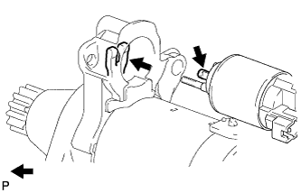
Apply high-temperature grease to the plunger and the lever.
Text in Illustration High-temperature grease -
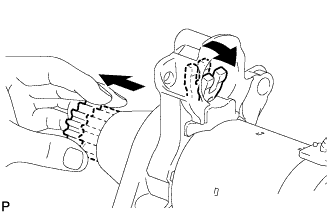
Pull the pinion gear and push down the lever.
-
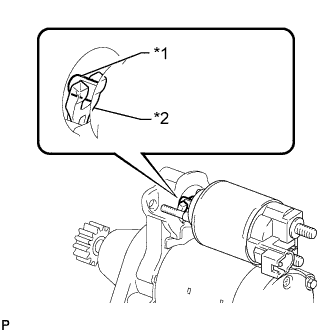
Text in Illustration *1 Plunger *2 Lever Temporarily install the magnet starter switch assembly by hooking the plunger into the upper side of the pinion drive lever.
-
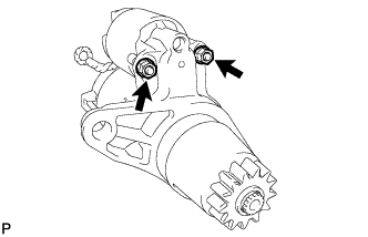
Install the magnet starter switch assembly with the 2 nuts.
- Torque:
- 7.5 N*m { 76 kgf*cm, 66 in.*lbf }
-
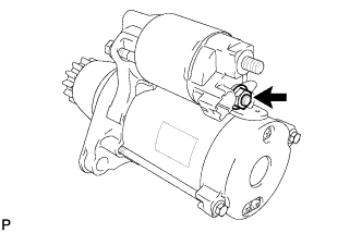
Connect the lead wire to the magnet starter switch assembly with the nut.
- Torque:
- 10 N*m { 102 kgf*cm, 7 ft.*lbf }
-