AFS (ADAPTIVE FRONT-LIGHTING SYSTEM) AFS OFF Switch Circuit
DESCRIPTION
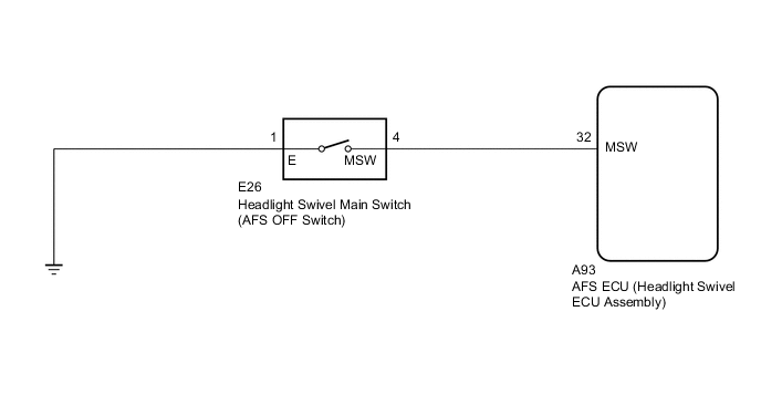
When the headlight swivel main switch is pushed (ON), the AFS ECU (headlight swivel ECU assembly) will cancel the intelligent AFS control and turn on the AFS OFF indicator light.
WIRING DIAGRAM
CAUTION / NOTICE / HINT
Note
If the AFS ECU (headlight swivel ECU assembly) has been replaced, it is necessary to synchronize the vehicle information and initialize the AFS ECU (headlight swivel ECU assembly).
PROCEDURE
-
READ VALUE USING GTS
-
Connect the GTS to the DLC3.
-
Turn the ignition switch to ON.
-
Turn the GTS on.
-
Enter the following menus: Body Electrical / AFS / Data List.
-
Read the display on the GTS.
Body Electrical > AFS > Data ListTester Display Measurement Item Range Normal Condition Diagnostic Note AFS OFF Switch Headlight swivel main switch signal ON or OFF ON: Headlight swivel main switch pushed
OFF: Headlight swivel main switch not pushed
-
Body Electrical > AFS > Data ListTester Display AFS OFF Switch OK Normal condition listed above is displayed. Result Proceed to OK NG
OK 
PROCEED TO NEXT SUSPECTED AREA SHOWN IN PROBLEM SYMPTOMS TABLE Click here
NG 
-
-
INSPECT HEADLIGHT SWIVEL MAIN SWITCH
-
Remove the headlight swivel main switch.
-
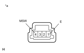
*a Component without harness connected
(Headlight Swivel Main Switch)
Measure the resistance according to the value(s) in the table below.
Standard Resistance Tester Connection Condition Specified Condition 4 (MSW) - 1 (E) Not pushed (OFF) 10 kΩ or higher Pushed (ON) Below 1 Ω Result Proceed to OK NG
NG
REPLACE HEADLIGHT SWIVEL MAIN SWITCH Click here
OK
-
-
CHECK HARNESS AND CONNECTOR (HEADLIGHT SWIVEL MAIN SWITCH - AFS ECU (HEADLIGHT SWIVEL ECU ASSEMBLY) AND BODY GROUND)
-
Disconnect the A93 AFS ECU (headlight swivel ECU assembly) connector.
-
Disconnect the E26 headlight swivel main switch connector.
-
Measure the resistance according to the value(s) in the table below.
Standard Resistance Tester Connection Condition Specified Condition A93-32 (MSW) - E26-4 (MSW) Always Below 1 Ω A93-32 (MSW) - Body ground Always 10 kΩ or higher E26-1 (E) - Body ground Always Below 1 Ω Result Proceed to OK NG
OK
REPLACE AFS ECU (HEADLIGHT SWIVEL ECU ASSEMBLY) Click here
NG
REPAIR OR REPLACE HARNESS OR CONNECTOR
-