AUTOMATIC HIGH BEAM SYSTEM TERMINALS OF ECU
-
CHECK AFS ECU (HEADLIGHT SWIVEL ECU ASSEMBLY)

-
Disconnect the A93 AFS ECU (headlight swivel ECU assembly) connector.
-
Measure the resistance according to the value(s) in the table below.
Terminal No. (Symbol) Wiring Color Terminal Description Condition Specified Condition A93-22 (E1) - Body ground W-B - Body ground AFS ECU (headlight swivel ECU assembly) ground Always Below 1 Ω If the result is not as specified, there may be a malfunction in the wire harness.
-
Measure the voltage according to the value(s) in the table below.
Terminal No. (Symbol) Wiring Color Terminal Description Condition Specified Condition A93-15 (IG) - Body ground L - Body ground AFS ECU (headlight swivel ECU assembly) power supply Ignition switch off Below 1 V Ignition switch ON 11 to 14 V If the result is not as specified, there may be a malfunction in the wire harness.
-
Reconnect the A93 AFS ECU (headlight swivel ECU assembly) connector.
-
Measure the voltage and check for pulses according to the value(s) in the table below.
Terminal No. (Symbol) Wiring Color Terminal Description Condition Specified Condition A93-30 (LHT) - A93-22 (E1) LG - W-B LIN communication Ignition switch off Below 1 V Ignition switch ON Pulse generation A93-12 (CANH) - A93-22 (E1) Y - W-B CAN communication Ignition switch off Below 1 V Ignition switch ON Pulse generation A93-13 (CANL) - A93-22 (E1) W - W-B CAN communication Ignition switch off Below 1 V Ignition switch ON Pulse generation If the result is not as specified, the AFS ECU (headlight swivel ECU assembly) may be malfunctioning.
-
-
CHECK INSTRUMENT PANEL JUNCTION BLOCK ASSEMBLY AND MAIN BODY ECU (MULTIPLEX NETWORK BODY ECU)
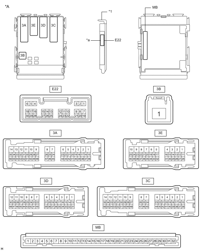
*A Main Body ECU (Multiplex Network Body ECU) with 1 Connector - - *1 Main Body ECU (Multiplex Network Body ECU) - - *a 1 Connector - - 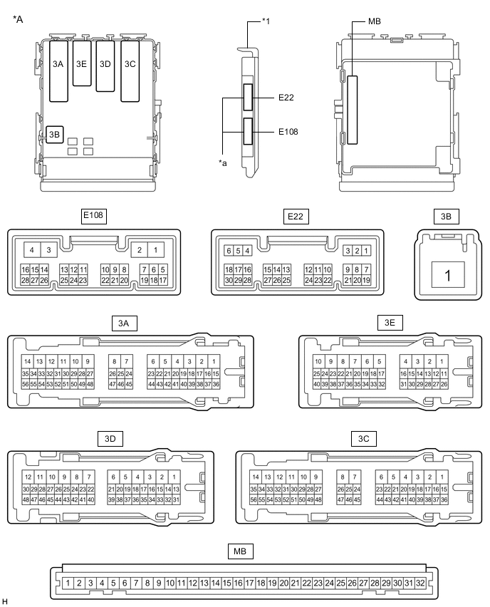
*A Main Body ECU (Multiplex Network Body ECU) with 2 Connectors - - *1 Main Body ECU (Multiplex Network Body ECU) - - *a 2 Connectors - -
-
Measure the voltage and check for pulses according to the value(s) in the table below.
Terminal No. (Symbol) Wiring Color Terminal Description Condition Specified Condition 3A-54 - Body ground LG - Body ground High beam headlight drive output Dimmer switch in high or high flash position Below 1 V Dimmer switch in low position 11 to 14 V E22-5 (HU) - Body ground P - Body ground Dimmer switch high position signal input Dimmer switch in high position Below 1 V Dimmer switch not in high position 11 to 14 V E22-20 (CLTB) - E22-22 (CLTE) W - V Automatic light control sensor power supply output Ignition switch off Below 1 V Ignition switch ON, light control switch in AUTO position 11 to 14 V E22-21 (CLTS) - Body ground Y - Body ground Automatic light control sensor signal input Ignition switch off Below 1 V Automatic light control system operating Pulse generation
(See waveform 1)
E22-28 (A) - Body ground V - Body ground Light control switch AUTO position signal input Light control switch in AUTO position Below 1 V Light control switch not in AUTO position Pulse generation E22-14 (CANH) - Body ground G - Body ground CAN Communication Ignition switch off Below 1 V Ignition switch ON Pulse generation E22-13 (CANL) - Body ground W - Body ground CAN Communication Ignition switch off Below 1 V Ignition switch ON Pulse generation If the result is not as specified, the main body ECU (multiplex network body ECU) or instrument panel junction block assembly may be malfunctioning.
-
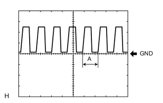
Waveform 1
Item Content Tool setting 5 V/DIV., 5 ms./DIV. Tech Tips
If the ambient light becomes brighter, width A becomes narrower.
-
-
-
CHECK INNER REAR VIEW MIRROR ASSEMBLY

-
Disconnect the O3 inner rear view mirror assembly connector.
-
Measure the resistance according to the value(s) in the table below.
Terminal No. (Symbol) Wiring Color Terminal Description Condition Specified Condition O3-1 (E) - Body ground W-B - Body ground Inner rear view mirror assembly ground Always Below 1 Ω If the result is not as specified, there may be a malfunction in the wire harness.
-
Measure the voltage according to the value(s) in the table below.
Terminal No. (Symbol) Wiring Color Terminal Description Condition Specified Condition O3-4 (IG) - Body ground L - Body ground Inner rear view mirror assembly power supply Ignition switch off Below 1 V Ignition switch ON 11 to 14 V If the result is not as specified, there may be a malfunction in the wire harness.
-
Reconnect the O3 inner rear view mirror assembly connector.
-
Measure the voltage or check for pulses according to the value(s) in the table below.
Terminal No. (Symbol) Wiring Color Terminal Description Condition Specified Condition O3-5 (LIN) - O3-1 (E) LG - W-B LIN communication Ignition switch off Below 1 V Automatic high beam system operating Pulse generation
(See waveform 1)
If the result is not as specified, the inner rear view mirror assembly may be malfunctioning.
-
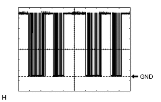
Waveform 1
Item Content Tool setting 2 V/DIV., 10 ms./DIV.
-
-