LIGHTING SYSTEM TERMINALS OF ECU
-
CHECK INSTRUMENT PANEL JUNCTION BLOCK ASSEMBLY AND MAIN BODY ECU (MULTIPLEX NETWORK BODY ECU)
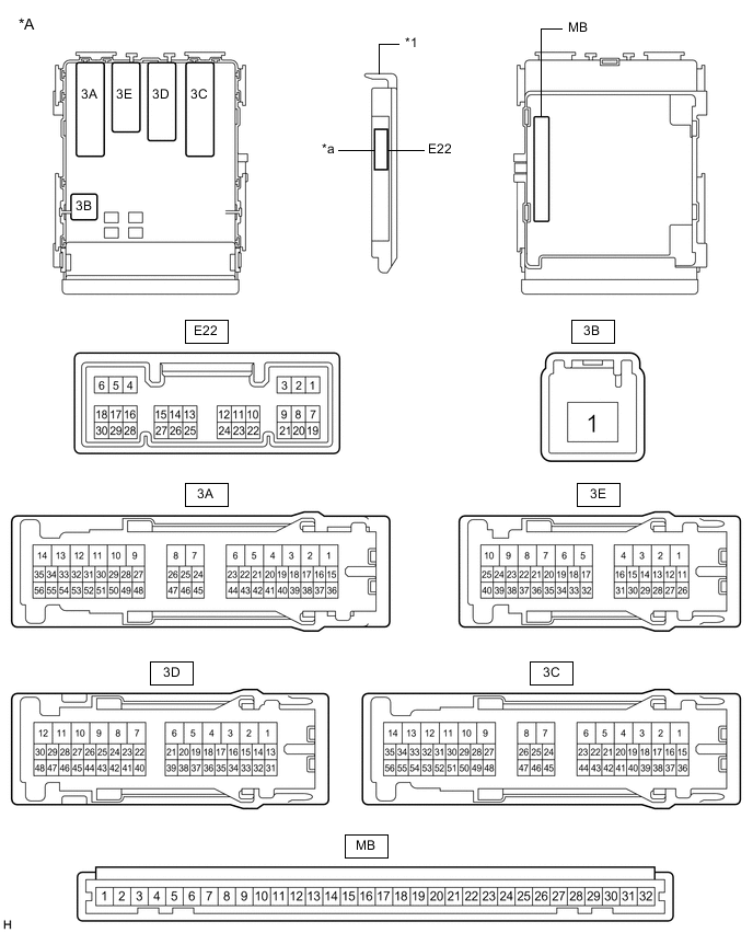
*A Main Body ECU (Multiplex Network Body ECU) with 1 Connector - - *1 Main Body ECU (Multiplex Network Body ECU) - - *a 1 Connector - - 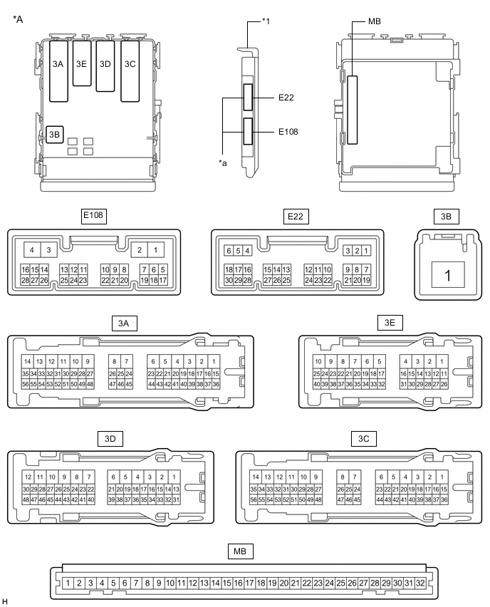
*A Main Body ECU (Multiplex Network Body ECU) with 2 Connectors - - *1 Main Body ECU (Multiplex Network Body ECU) - - *a 2 Connectors - -
-
Disconnect the instrument panel junction block assembly and main body ECU (multiplex network body ECU) connectors.
-
Measure the voltage according to the value(s) in the table below.
Terminal No. (Symbol) Wiring Color Terminal Description Condition Specified Condition 3A-43 (BECU) - Body ground G - Body ground Battery power supply Always 11 to 14 V 3B-1 - Body ground W - Body ground Battery power supply Always 11 to 14 V If the result is not as specified, there may be a malfunction in the wire harness.
-
Measure the resistance according to the value(s) in the table below.
Terminal No. (Symbol) Wiring Color Terminal Description Condition Specified Condition 3D-12 (GND1) - Body ground W-B - Body ground Ground Always Below 1 Ω If the result is not as specified, there may be a malfunction in the wire harness.
-
Reconnect the instrument panel junction block assembly and main body ECU (multiplex network body ECU) connectors.
-
Measure the voltage and check for pulses according to the value(s) in the table below.
Terminal No. (Symbol) Wiring Color Terminal Description Condition Specified Condition 3A-7 - Body ground G - Body ground Clearance light RH drive output Light control switch in tail or head position 11 to 14 V Light control switch off Below 1 V 3A-8 - Body ground G - Body ground Clearance light LH drive output Light control switch in tail or head position 11 to 14 V Light control switch off Below 1 V 3E-17 - Body ground G - Body ground Taillight RH drive output Light control switch in tail or head position 11 to 14 V Light control switch off Below 1 V 3E-32 - Body ground G - Body ground Taillight LH drive output Light control switch in tail or head position 11 to 14 V Light control switch off Below 1 V 3A-35 (HRLY) - Body ground B - Body ground*1
V - Body ground*2
Headlight relay drive output Light control switch in head position Below 1 V Light control switch not in head position 11 to 14 V 3A-53 (DRL) - Body ground*6 P - Body ground Daytime running light system drive output Daytime running light system operating Below 1 V Daytime running light system not operating 11 to 14 V 3E-40 - Body ground*5 SB - Body ground Rear fog light drive output Light control switch in tail or head position, fog light switch in rear position 11 to 14 V Light control switch in tail or head position, fog light switch off Below 1 V 3D-10 - Body ground*3 G - Body ground Front fog light drive output Always 11 to 14 V 3C-43 (FFGO) - Body ground*3 L - Body ground Front fog light relay drive output Light control switch in tail or head position, fog light switch in front position Below 1 V Light control switch in tail or head position, fog light switch off 11 to 14 V 3A-54 (DIM) - Body ground LG - Body ground High beam headlight drive output Dimmer switch in high or high flash position Below 1 V Dimmer switch in low position 11 to 14 V 3D-47 - Body ground*3 L - Body ground Front fog relay power supply output Light control switch in tail or head position 11 to 14 V Light control switch off Below 1 V 3E-27 - Body ground B - Body ground Parking brake switch input Parking brake switch on Below 1 V Parking brake switch off 11 to 14 V E22-5 (HU) - Body ground P - Body ground Dimmer switch high position signal input Dimmer switch in high position Below 1 V Dimmer switch not in high position Pulse generation E22-8 (HF) - Body ground R - Body ground Dimmer switch high flash position signal input Dimmer switch in high flash position Below 1 V Dimmer switch not in high flash position Pulse generation E22-20 (CLTB) - E22-22 (CLTE)*4 W - V Automatic light control sensor power supply output Ignition switch off Below 1 V Ignition switch ON 11 to 14 V E22-21 (CLTS) - Body ground*4 Y - Body ground Automatic light control sensor signal input Ignition switch off Below 1 V Automatic light control system operating Pulse generation
(See waveform 1)
E22-1 (RFOG) - Body ground*5 SB - Body ground Fog light switch rear position input Fog light switch in rear position Below 1 V Fog light switch off Pulse generation E22-27 (FFOG) - Body ground*3 G - Body ground Fog light switch front position input Fog light switch in front position Below 1 V Fog light switch off Pulse generation E22-28 (A) - Body ground*4 V - Body ground Light control switch AUTO position signal input Light control switch in AUTO position Below 1 V Light control switch not in AUTO position Pulse generation E22-29 (HEAD) - Body ground L - Body ground Light control switch head position input Light control switch in head position Below 1 V Light control switch not in head position, ignition switch off Pulse generation E22-30 (TAIL) - Body ground W - Body ground Light control switch tail position signal input Light control switch in tail or head position Below 1 V Light control switch not in tail or head position, ignition switch off Pulse generation
-
*1: w/ Headlight Cleaner
-
*2: w/o Headlight Cleaner
-
*3: w/ Front Fog Light
-
*4: w/ Automatic Light Control
-
*5: w/ Rear Fog Light
-
*6: w/ Daytime Running Light
If the result is not as specified, the main body ECU (multiplex network body ECU) or instrument panel junction block assembly may be malfunctioning.
-
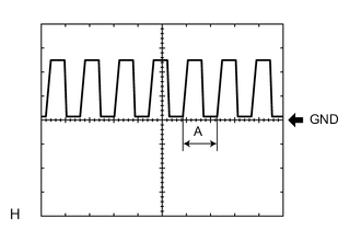
Waveform 1
Item Content Tool setting 5 V/DIV., 5 ms./DIV. Tech Tips
If the ambient light becomes brighter, width A becomes narrower.
-
-
-
CHECK COMBINATION METER ASSEMBLY
-
Measure the voltage according to the value(s) in the table below.
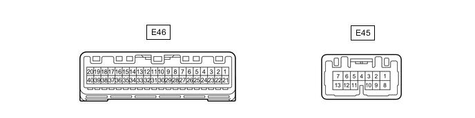
Terminal No. (Symbol) Wiring Color Terminal Description Condition Specified Condition E45-3 (HAZ) - Body ground GR - Body ground Hazard warning signal switch input Ignition switch ON, hazard warning switch off 11 to 14 V Ignition switch ON, hazard warning switch on Below 1 V E45-9 (ER) - Body ground P - Body ground Turn signal switch right signal input Turn signal switch in neutral position 11 to 14 V Turn signal switch in right turn position Below 1 V E45-10 (EL) - Body ground LG - Body ground Turn signal switch left signal input Turn signal switch in neutral position 11 to 14 V Turn signal switch in left turn position Below 1 V
-
-
CHECK HEADLIGHT SWIVEL ECU ASSEMBLY

-
Measure the voltage and check for pulses according to the value(s) in the table below.
Terminal No. (Symbol) Wiring Color Terminal Description Condition Specified Condition A93-6 (INL) - Body ground P - Body ground LED headlight LH operation signal input Ignition switch ON, light control switch off 4.5 to 5.5 V Ignition switch ON, light control switch in head position Pulse generation A93-7 (INR) - Body ground G - Body ground LED headlight RH operation signal input Ignition switch ON, light control switch off 4.5 to 5.5 V Ignition switch ON, light control switch in head position Pulse generation
-
If the result is not as specified, the headlight swivel ECU assembly may be malfunctioning.
-
-