WIPER AND WASHER SYSTEM Speed Signal Circuit
DESCRIPTION
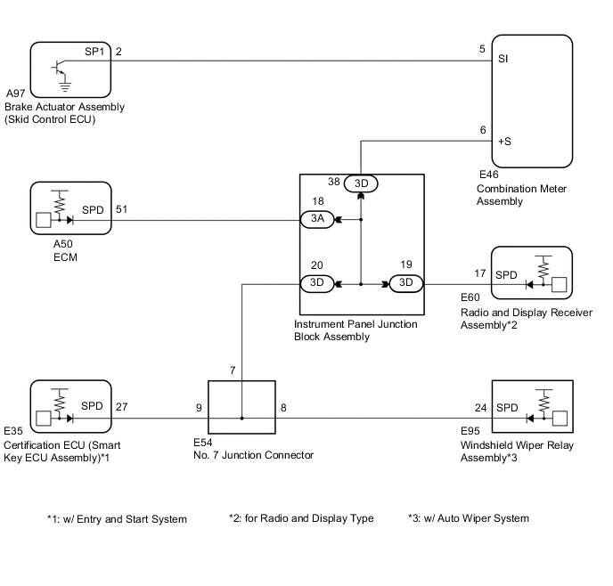
The windshield wiper relay assembly receives a vehicle speed signal from the combination meter assembly to control the automatic windshield wiper system.
A voltage of 12 V or 5 V is output from the combination meter assembly and then input to the skid control ECU.
A voltage of 12 V or 5 V is output from each ECU or relay and then input to the combination meter assembly.
The signal is changed to a pulse signal at the transistor in the combination meter assembly.
Each ECU controls the respective system based on the pulse signal.
If a short occurs in any of the ECUs or in the wire harness connected to an ECU, all systems in the following diagram will not operate normally.
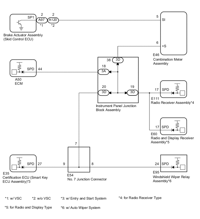
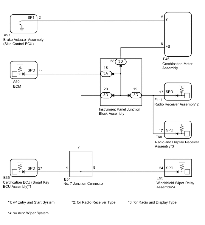
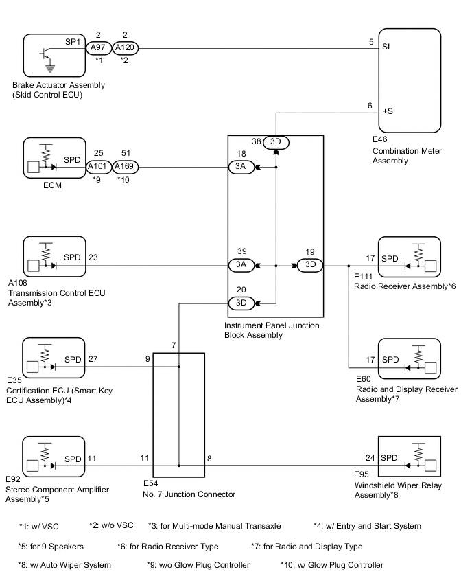
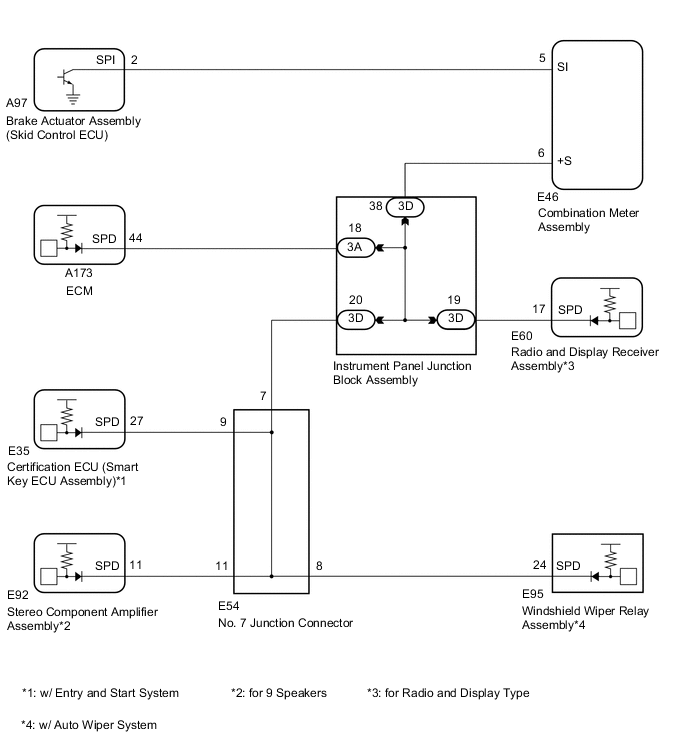
WIRING DIAGRAM
-
for 1NR-FE
-
for 1ZR-FAE
-
for 1ND-TV
-
for 1ZR-FE, 2ZR-FE

-
for 8NR-FTS
-
for 1WW
PROCEDURE
-
INSPECT COMBINATION METER ASSEMBLY (OUTPUT WAVEFORM)
-
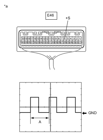
*a Component with harness connected
(Combination Meter Assembly)
Check the output waveform.
-
Remove the combination meter assembly with the connector still connected.
-
Connect an oscilloscope to terminal E46-6 (+S) and body ground.
-
Turn the ignition switch to ON.
-
Check the signal waveform according to the condition(s) in the table below.
Item Condition Tool setting 5 V/DIV., 20 ms./DIV. Vehicle condition Wheel being rotated OK The waveform is displayed as shown in the illustration. Tech Tips
When the system is functioning normally, one wheel revolution generates 4 pulses. As the vehicle speed increases, the width indicated by (A) in the illustration narrows.
Result Result OK NG -
NG 
GO TO METER / GAUGE SYSTEM Click here
OK 
-
-
CHECK HARNESS AND CONNECTOR (WINDSHIELD WIPER RELAY ASSEMBLY - COMBINATION METER ASSEMBLY)
-
Disconnect the E95 windshield wiper relay assembly connector.
-
Disconnect the E46 combination meter assembly connector.
-
Measure the resistance according to the value(s) in the table below.
Standard Resistance Tester Connection Condition Specified Condition E95-24 (SPD) - E46-6 (+S) Always Below 1 Ω Result Result OK NG
OK
PROCEED TO NEXT SUSPECTED AREA SHOWN IN PROBLEM SYMPTOMS TABLE Click here
NG
REPAIR OR REPLACE HARNESS OR CONNECTOR
-