WINDOW DEFOGGER SYSTEM Rear Window Defogger System does not Operate
DESCRIPTION
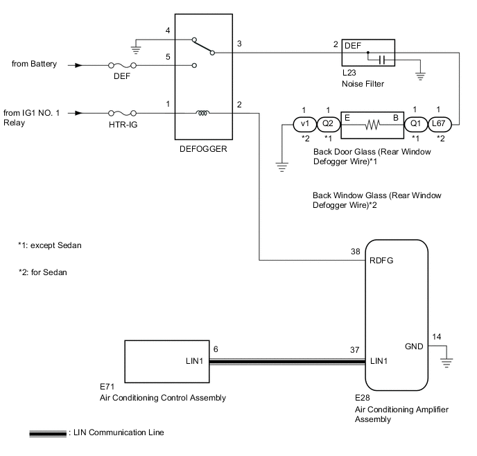
When the rear window defogger switch on the air conditioning control assembly is pressed, the operation signal is transmitted to the air conditioning amplifier assembly via LIN communication. When the air conditioning amplifier assembly receives the signal, it turns on the defogger relay to operate the window defogger system.
WIRING DIAGRAM
CAUTION / NOTICE / HINT
Note
-
Inspect the fuses for circuits related to this system before performing the following procedure.
-
If the battery voltage becomes low, window defogger system operation is canceled to prioritize supplying power to the power steering system.
PROCEDURE
-
CHECK AIR CONDITIONING SYSTEM
-
Check the air conditioning system.
Tech Tips
Both the window defogger system operation signal and air conditioning system operation signal are transmitted to the air conditioning amplifier assembly via the same communication line.
OK The air conditioning system operates normally. Result Proceed to OK NG
NG 
GO TO AIR CONDITIONING SYSTEM Click here
OK 
-
-
PERFORM ACTIVE TEST USING GTS
-
Connect the GTS to the DLC3.
-
Turn the ignition switch to ON.
-
Turn the GTS on.
-
Enter the following menus: Body Electrical / Air Conditioner / Active Test.
-
Perform the Active Test according to the display on the GTS.
Body Electrical > Air Conditioner > Active TestTester Display Measurement Item Control Range Diagnostic Note Defogger Relay (Rear) Rear window defogger wire OFF or ON -
Body Electrical > Air Conditioner > Active TestTester Display Defogger Relay (Rear) OK The window defogger system operates normally. Result Proceed to OK NG
NG 
INSPECT DEFOGGER RELAY Click here
OK
-
-
REPLACE AIR CONDITIONING AMPLIFIER ASSEMBLY
-
Replace the air conditioning amplifier assembly with a new or known good one.
-
Check that the window defogger system operates normally.
OK The window defogger system operates normally. Result Proceed to OK NG
OK
END (AIR CONDITIONING AMPLIFIER ASSEMBLY WAS DEFECTIVE)
NG
REPLACE AIR CONDITIONING CONTROL ASSEMBLY Click here
-
-
INSPECT DEFOGGER RELAY
-
Inspect the defogger relay.
Result Proceed to OK NG
NG
REPLACE DEFOGGER RELAY
OK
-
-
CHECK HARNESS AND CONNECTOR (DEFOGGER RELAY - IG1 NO. 1 RELAY AND BATTERY)
-
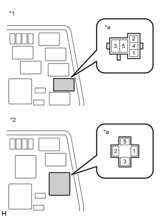
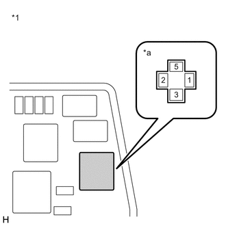
*1 Engine Room Relay Block and Junction Block Assembly (except Sedan) *2 Engine Room Relay Block and Junction Block Assembly (for Sedan) *a Defogger Relay Holder Remove the defogger relay from the engine room relay block and junction block assembly.
-
Measure the voltage according to the value(s) in the table below.
Standard Voltage Tester Connection Condition Specified Condition Defogger relay holder terminal-1 - Body ground Ignition switch ON 11 to 14 V Defogger relay holder terminal-5 - Body ground Always 11 to 14 V Result Proceed to OK NG
NG
REPAIR OR REPLACE HARNESS OR CONNECTOR
OK
-
-
CHECK HARNESS AND CONNECTOR (DEFOGGER RELAY - AIR CONDITIONING AMPLIFIER ASSEMBLY)
-
*1 Engine Room Relay Block and Junction Block Assembly (except Sedan) *2 Engine Room Relay Block and Junction Block Assembly (for Sedan) *a Defogger Relay Holder Disconnect the E28 air conditioning amplifier assembly connector.
-
Measure the resistance according to the value(s) in the table below.
Standard Resistance Tester Connection Condition Specified Condition Defogger relay holder terminal-2 - E28-38 (RDFG) Always Below 1 Ω Defogger relay holder terminal-2 - Body ground Always 10 kΩ or higher Result Proceed to OK NG
NG
REPAIR OR REPLACE HARNESS OR CONNECTOR
OK
-
-
CHECK AIR CONDITIONING AMPLIFIER ASSEMBLY
-
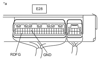
*a Component with harness connected
(Air Conditioning Amplifier Assembly)
Reconnect the E28 air conditioning amplifier assembly connector.
-
Reinstall the defogger relay.
-
Remove the air conditioning amplifier assembly with its connectors still connected.
-
Measure the voltage according to the value(s) in the table below.
Standard Voltage Tester Connection Condition Specified Condition E28-38 (RDFG) - E28-14 (GND) Ignition switch ON, rear window defogger switch on Below 1 V E28-38 (RDFG) - E28-14 (GND) Ignition switch ON, rear window defogger switch off 11 to 14 V Result Result Proceed to OK (except Sedan) A OK (for Sedan) B NG C
B
CHECK HARNESS AND CONNECTOR (BACK WINDOW GLASS (REAR WINDOW DEFOGGER WIRE) - DEFOGGER RELAY AND BODY GROUND) Click here
C
REPLACE AIR CONDITIONING AMPLIFIER ASSEMBLY Click here
A
-
-
CHECK HARNESS AND CONNECTOR (BACK DOOR GLASS (REAR WINDOW DEFOGGER WIRE) - DEFOGGER RELAY AND BODY GROUND)
-
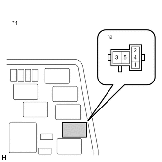
*1 Engine Room Relay Block and Junction Block Assembly *a Defogger Relay Holder Disconnect the Q1 and Q2 back door glass (rear window defogger wire) connectors.
-
Remove the defogger relay from the engine room relay block and junction block assembly.
-
Measure the resistance according to the value(s) in the table below.
Standard Resistance Tester Connection Condition Specified Condition Q1-1 (B) - Defogger relay holder terminal-3 Always Below 1 Ω Q2-1 (E) - Body ground Always Below 1 Ω Q1-1 (B) - Body ground Always 10 kΩ or higher Result Proceed to OK NG
OK
REPAIR OR REPLACE BACK DOOR GLASS (REAR WINDOW DEFOGGER WIRE) for Hatchback: Click here
REPAIR OR REPLACE BACK DOOR GLASS (REAR WINDOW DEFOGGER WIRE) for Wagon: Click hereNG
REPAIR OR REPLACE HARNESS OR CONNECTOR
-
-
CHECK HARNESS AND CONNECTOR (BACK WINDOW GLASS (REAR WINDOW DEFOGGER WIRE) - DEFOGGER RELAY AND BODY GROUND)
-
*1 Engine Room Relay Block and Junction Block Assembly *a Defogger Relay Holder Disconnect the L67 and v1 back window glass (rear window defogger wire) connectors.
-
Remove the defogger relay from the engine room relay block and junction block assembly.
-
Measure the resistance according to the value(s) in the table below.
Standard Resistance Tester Connection Condition Specified Condition L67-1 (B) - Defogger relay holder terminal-3 Always Below 1 Ω v1-1 (E) - Body ground Always Below 1 Ω L67-1 (B) - Body ground Always 10 kΩ or higher Result Proceed to OK NG
OK
REPAIR OR REPLACE BACK WINDOW GLASS (REAR WINDOW DEFOGGER WIRE) Click here
NG
REPAIR OR REPLACE HARNESS OR CONNECTOR
-