HEATER SWITCH INSPECTION
PROCEDURE
-
INSPECT HEATER SWITCH ASSEMBLY
-
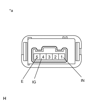
*a Component without harness connected
(Heater Switch Assembly)
Measure the resistance.
-
Measure the resistance according to the value(s) in the table below.
Standard Resistance Tester Connection Condition Specified Condition 4 (IG) - 1 (IN) Heater switch assembly: On Below 1 Ω 4 (IG) - 1 (IN) Heater switch assembly: Off 10 kΩ or higher
-
-
Check the operation indicator.
-
Turn the heater switch assembly on.
-
Connect a positive (+) lead from the battery to terminal 4 (IG) and a negative (-) lead to terminal 5 (E), and check that the operation indicator comes on.
OK Indicator comes on. If the result is not as specified, replace the heater switch assembly.
-
-