SOLAR SENSOR INSPECTION
PROCEDURE
-
INSPECT COOLER (SOLAR SENSOR) THERMISTOR (for Single Type)
-
Check the wire harness
-
Disconnect the E28 air conditioning amplifier assembly connector.
-
Disconnect the F4 cooler (solar sensor) thermistor connector.
-
Measure the resistance according to the value(s) in the table below.
Standard Resistance Tester Connection Condition Specified Condition F4-1 (SS+) - E28-30 (S5-1) Always Below 1 Ω F4-2 (SS-) - E28-33 (TSD) Always Below 1 Ω F4-1 (SS+) - Body ground Always 10 kΩ or higher F4-2 (SS-) - Body ground Always 10 kΩ or higher
-
If the resistance is not as specified, repair the wire harness.
-
-
Reconnect the E28 air conditioning amplifier assembly connector.
-
Turn the ignition switch to ON.
-
Measure the voltage according to the value(s) in the table below.
Standard Voltage Tester Connection Condition Specified Condition F4-1 (SS+) - F4-2 (SS-) Ignition switch off Below 1 V F4-1 (SS+) - F4-2 (SS-) Ignition switch ON 4.75 to 5.25 V
-
If the voltage is not as specified, replace the air conditioning amplifier assembly.
-
-
-
Check the cooler (solar sensor) thermistor.
-
Reconnect the connector to the cooler (solar sensor) thermistor.
-
Turn the ignition switch to ON.
-
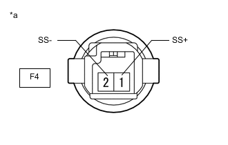
*a Component with harness connected
(Cooler (Solar Sensor) Thermistor))
Measure the voltage according to the value(s) in the table below.
Standard Voltage Tester Connection Condition Specified Condition F4-1 (SS+) - F4-2 (SS-) Sensor is subjected to electric light 0.8 to 4.3 V F4-1 (SS+) - F4-2 (SS-) Sensor is covered with a cloth Below 0.8 V Note
-
The connection procedure for using a digital tester such as a TOYOTA electrical tester is shown above. When using an analog tester, connect the negative (-) lead to terminal 1 and the positive (+) lead to terminal 2 of the cooler (solar sensor) thermistor.
-
Do not bring the positive and negative tester probes too close to each other as a short circuit may occur.
Tech Tips
-
Use an incandescent light for inspection. Bring it within about 30 cm (11.8 in.) of the cooler (solar sensor) thermistor.
-
As the inspection light is moved away from the sensor, the voltage decreases.
-
Check from the rear of the connector while it is connected to the cooler (solar sensor) thermistor.
-
If the voltage is not as specified, replace the cooler (solar sensor) thermistor.
-
-
-
-
INSPECT COOLER (SOLAR SENSOR) THERMISTOR (for Dual Type)
-
Check the wire harness
-
Disconnect the E28 air conditioning amplifier assembly connector.
-
Disconnect the F1 cooler (solar sensor) thermistor connector.
-
Measure the resistance according to the value(s) in the table below.
Standard Resistance Tester Connection Condition Specified Condition F1-1 (S5) - E28-30 (S5-1) Always Below 1 Ω F1-3 (TSD) - E28-33 (TSD)*A Always Below 1 Ω F1-2 (TSD) - E28-33 (TSD)*B Always Below 1 Ω F1-2 (TSP) - E28-32 (TSP)*A Always Below 1 Ω F1-3 (TSP) - E28-32 (TSP)*B Always Below 1 Ω F1-1 (S5) - Body ground Always 10 kΩ or higher F1-3 (TSD) - Body ground*A Always 10 kΩ or higher F1-2 (TSD) - Body ground*B Always 10 kΩ or higher F1-2 (TSP) - Body ground*A Always 10 kΩ or higher F1-3 (TSP) - Body ground*B Always 10 kΩ or higher
-
*A: for LHD
-
*B: for RHD
-
If the resistance is not as specified, repair the wire harness.
-
-
Reconnect the E28 air conditioning amplifier assembly connector.
-
Turn the ignition switch to ON.
-
Measure the voltage according to the value(s) in the table below.
Standard Voltage Tester Connection Condition Specified Condition F1-1 (S5) - F1-3 (TSD)*A Ignition switch off Below 1 V F1-1 (S5) - F1-3 (TSD)*A Ignition switch ON 4.75 to 5.25 V F1-1 (S5) - F1-2 (TSD)*B Ignition switch off Below 1 V F1-1 (S5) - F1-2 (TSD)*B Ignition switch ON 4.75 to 5.25 V F1-1 (S5) - F1-2 (TSP)*A Ignition switch off Below 1 V F1-1 (S5) - F1-2 (TSP)*A Ignition switch ON 4.75 to 5.25 V F1-1 (S5) - F1-3 (TSP)*B Ignition switch off Below 1 V F1-1 (S5) - F1-3 (TSP)*B Ignition switch ON 4.75 to 5.25 V
-
*A: for LHD
-
*B: for RHD
-
If the voltage is not as specified, replace the air conditioning amplifier assembly.
-
-
-
Check the cooler (solar sensor) thermistor.
-
Reconnect the connector to the cooler (solar sensor) thermistor.
-
Turn the ignition switch to ON.
-
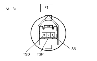
*A for LHD *a Component with harness connected
(Cooler (Solar Sensor) Thermistor)
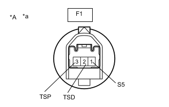
*A for RHD *a Component with harness connected
(Cooler (Solar Sensor) Thermistor)
Measure the voltage according to the value(s) in the table below.
Standard Voltage for LHD Tester Connection Condition Specified Condition F1-1 (S5) - F1-3 (TSD) Sensor is subjected to electric light 0.8 to 4.3 V F1-1 (S5) - F1-3 (TSD) Sensor is covered with a cloth Below 0.8 V F1-1 (S5) - F1-2 (TSP) Sensor is subjected to electric light 0.8 to 4.3 V F1-1 (S5) - F1-2 (TSP) Sensor is covered with a cloth Below 0.8 V Note
-
The connection procedure for using a digital tester such as a TOYOTA electrical tester is shown above. When using an analog tester, connect the negative (-) lead to terminal 1 and the positive (+) lead to terminal 2 or 3 of the cooler (solar sensor) thermistor.
-
Do not bring the positive and negative tester probes too close to each other as a short circuit may occur.
Standard Voltage for RHD Tester Connection Condition Specified Condition F1-1 (S5) - F1-2 (TSD) Sensor is subjected to electric light 0.8 to 4.3 V F1-1 (S5) - F1-2 (TSD) Sensor is covered with a cloth Below 0.8 V F1-1 (S5) - F1-3 (TSP) Sensor is subjected to electric light 0.8 to 4.3 V F1-1 (S5) - F1-3 (TSP) Sensor is covered with a cloth Below 0.8 V Note
-
The connection procedure for using a digital tester such as a TOYOTA electrical tester is shown above. When using an analog tester, connect the negative (-) lead to terminal 1 and the positive (+) lead to terminal 2 or 3 of the cooler (solar sensor) thermistor.
-
Do not bring the positive and negative tester probes too close to each other as a short circuit may occur.
Tech Tips
-
Use an incandescent light for inspection. Bring it within about 30 cm (11.8 in.) of the cooler (solar sensor) thermistor.
-
As the inspection light is moved away from the sensor, the voltage decreases.
-
Check from the rear of the connector while it is connected to the cooler (solar sensor) thermistor.
-
If the voltage is not as specified, replace the cooler (solar sensor) thermistor.
-
-
-