CONDENSER(except 1AD-FTV) INSTALLATION
PROCEDURE
-
INSTALL CONDENSER WITH RECEIVER ASSEMBLY
-
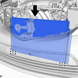
Engage the 2 guides to install the condenser with receiver assembly as shown in the illustration.
Note
Do not damage the condenser with receiver assembly or radiator when installing the condenser with receiver assembly.
Tech Tips
If a new condenser with receiver assembly is installed, add compressor oil to the condenser with receiver assembly as follows.
Capacity Add 40 cc (1.35 fl. oz.) Compressor Oil ND-OIL 8 or equivalent
-
-
CONNECT AIR CONDITIONER TUBE ASSEMBLY
-
Remove the vinyl tape from the air conditioner tube assembly and the connecting part of the condenser with receiver assembly.
-
Sufficiently apply compressor oil to a new O-ring and the fitting surface of the tube joint.
Compressor Oil ND-OIL 8 or equivalent -
Install the O-ring to the air conditioner tube assembly.
-
Install the air conditioner tube assembly to the condenser with receiver assembly with the bolt.
- Torque:
- 5.4 N*m { 55 kgf*cm, 48 in.*lbf }
-
-
CONNECT DISCHARGE HOSE SUB-ASSEMBLY
-
Remove the vinyl tape from the discharge hose sub-assembly and the connecting part of the condenser with receiver assembly.
-
Sufficiently apply compressor oil to a new O-ring and the fitting surface of the hose joint.
Compressor Oil ND-OIL 8 or equivalent -
Install the O-ring to the discharge hose sub-assembly.
-
Install the discharge hose sub-assembly to the condenser with receiver assembly with the bolt.
- Torque:
- 5.4 N*m { 55 kgf*cm, 48 in.*lbf }
-
-
INSTALL NO. 2 FAN SHROUD
-
Engage the 2 guides and 2 claws.
-
Install the No. 2 fan shroud with the 2 bolts.
- Torque:
- 7.0 N*m { 71 kgf*cm, 62 in.*lbf }
-
Engage the clamp to connect the No. 3 water by-pass hose to the No. 2 fan shroud.
-
-
INSTALL NO. 1 RADIATOR SUPPORT (for 1ND-TV)
-
INSTALL UPPER RADIATOR SUPPORT SUB-ASSEMBLY (for 1ND-TV)
-
INSTALL UPPER RADIATOR SUPPORT SUB-ASSEMBLY (for 1NR-FE)
-
INSTALL UPPER RADIATOR SUPPORT SUB-ASSEMBLY (for 1ZR-FAE)
-
CONNECT NO. 1 WATER HOSE CLAMP BRACKET (for 1ND-TV)
-
CONNECT NO. 1 WATER HOSE CLAMP BRACKET (for 1NR-FE)
-
CONNECT NO. 1 WATER HOSE CLAMP BRACKET (for 1ZR-FAE)
-
INSTALL BATTERY CLAMP SUB-ASSEMBLY
-
Install the battery clamp sub-assembly and battery clamp bolt with the bolt and nut.
- Torque:
- Bolt
- 16.5 N*m { 168 kgf*cm, 12 ft.*lbf }
- Nut
- 3.5 N*m { 36 kgf*cm, 31 in.*lbf }
-
-
INSTALL HEADLIGHT ASSEMBLY LH (for 1ND-TV)
-
INSTALL HEADLIGHT ASSEMBLY RH (for 1ND-TV)
Tech Tips
Use the same procedure as for the LH side.
-
INSTALL RADIATOR GRILLE SUB-ASSEMBLY
-
ADJUST HOOD SUB-ASSEMBLY
-
CHARGE AIR CONDITIONING SYSTEM WITH REFRIGERANT
-
WARM UP ENGINE
-
INSPECT FOR REFRIGERANT LEAK