COMPRESSOR(for 1ND-TV) INSTALLATION
PROCEDURE
-
INSPECT COMPRESSOR OIL
-
When replacing the compressor assembly with a new one, gradually discharge the inert gas (helium) from the service valve, and drain the following amount of oil before installation.
Standard (Capacity of oil to be drained when replacing) (The amount of compressor oil inside a new compressor assembly with pulley: 80 (+15) cc (2.71 (+0.507) fl.oz.)) - (The amount of compressor oil remaining in the removed compressor assembly with pulley) = The amount of compressor oil to be removed when replacing the compressor assembly with pulley Note
-
If a new compressor assembly with pulley is installed without removing the same amount of compressor oil as is remaining in the pipes, the amount of compressor oil will be excessive. This prevents heat exchange in the refrigerant cycle and will cause a refrigeration failure.
-
If the amount of compressor oil remaining in the removed compressor assembly with pulley is too low, check for compressor oil leakage.
-
Make sure to use ND-OIL 8 or equivalent compressor oil.
-
-
Remove the suction seal cap.
-
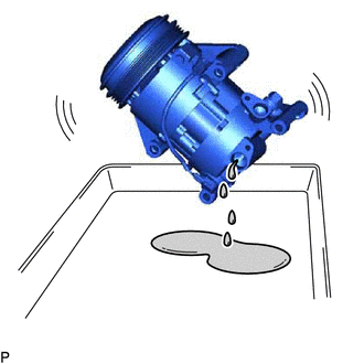
Position the suction port downward and slightly shake the compressor to drain the oil. (*1)
Note
Be careful not to allow compressor oil to adhere on the pulley.
-
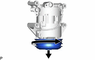
Position the DL pulley side downward and turn the pulley in the direction indicated by the arrow once in every 2 seconds 10 times. (*2)
Note
Keep your face away from the compressor port because turning the pulley may cause gas or oil to spew out.
-
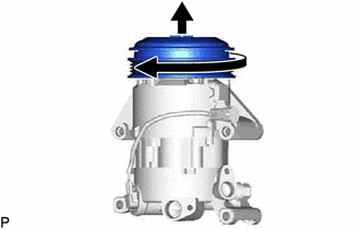
Quickly position the DL pulley side upward and turn the pulley in the direction indicated by the arrow once. (*3)
-
Repeat procedure (*1). (*4)
-
Repeat procedures (*2) through (*4) about 5 times to drain the standard amount of oil.
-
-
INSTALL COMPRESSOR ASSEMBLY WITH PULLEY
-
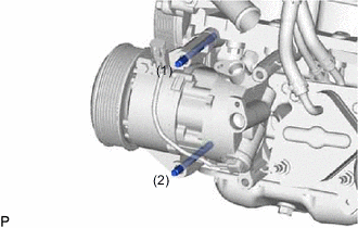
Using an E8 "TORX" socket, temporarily install the compressor assembly with pulley with the 2 stud bolts.
- Torque:
- 9.8 N*m { 100 kgf*cm, 87 in.*lbf }
Tech Tips
Tighten the stud bolts in the order shown in the illustration to temporarily install the compressor assembly with pulley.
-
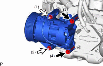

Bolt 
Nut Install the compressor assembly with pulley with the 2 bolts and 2 nuts.
- Torque:
- 25 N*m { 255 kgf*cm, 18 ft.*lbf }
Tech Tips
Tighten the bolts and nuts in the order shown in the illustration to install the compressor assembly with pulley.
-
Connect the connector.
-
-
CONNECT SUCTION HOSE SUB-ASSEMBLY
-
Remove the vinyl tape from the suction hose sub-assembly.
-
Sufficiently apply compressor oil to a new O-ring and the fitting surface of the compressor assembly with pulley.
Compressor Oil ND-OIL 8 or equivalent -
Install the O-ring onto the suction hose sub-assembly.
-
Install the suction hose sub-assembly to the compressor assembly with pulley with the bolt.
- Torque:
- 9.8 N*m { 100 kgf*cm, 87 in.*lbf }
-
-
CONNECT DISCHARGE HOSE SUB-ASSEMBLY
-
Remove the vinyl tape from the discharge hose sub-assembly.
-
Sufficiently apply compressor oil to a new O-ring and the fitting surface of the compressor assembly with pulley.
Compressor Oil ND-OIL 8 or equivalent -
Install the O-ring onto the discharge hose sub-assembly.
-
Install the discharge hose sub-assembly to the compressor assembly with pulley with the bolt.
- Torque:
- 9.8 N*m { 100 kgf*cm, 87 in.*lbf }
-
-
INSTALL V-RIBBED BELT
-
CHARGE AIR CONDITIONING SYSTEM WITH REFRIGERANT
-
WARM UP ENGINE
-
INSPECT FOR REFRIGERANT LEAK