AIR CONDITIONING UNIT REMOVAL
PROCEDURE
-
PRECAUTION
Note
Make sure to select face mode before disconnecting the cable from the negative (-) battery terminal.
-
RECOVER REFRIGERANT FROM REFRIGERATION SYSTEM (w/ Cooler System)
for HFC-134a (R134a):
for HFO-1234yf (R1234yf):
-
REMOVE WINDSHIELD WIPER MOTOR AND LINK ASSEMBLY (for 1WW, 1ND-TV)
-
REMOVE WATER GUARD PLATE LH (for 1WW, 1ND-TV)
for LHD:
for Sedan: Click here
for Hatchback, Wagon: Click here
for RHD:
for Sedan: Click here
for Hatchback, Wagon: Click here
-
REMOVE NO. 2 HEATER AIR DUCT SPLASH SHIELD SEAL (for 1WW, 1ND-TV)
for LHD:
for Sedan: Click here
for Hatchback, Wagon: Click here
for RHD:
for Sedan: Click here
for Hatchback, Wagon: Click here
-
REMOVE OUTER COWL TOP PANEL (for 1WW, 1ND-TV)
for LHD:
for Sedan: Click here
for Hatchback, Wagon: Click here
for RHD:
for Sedan: Click here
for Hatchback, Wagon: Click here
-
REMOVE COOLER CAP (w/o Cooler System)
-
Remove the bolt and cooler cap.
-
-
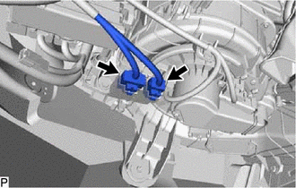
DISCONNECT SUCTION PIPE SUB-ASSEMBLY (w/ Cooler System)
-
w/o Sub-cool Accelerator:
-
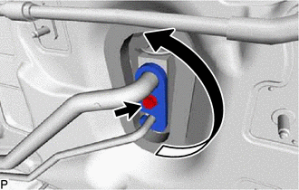
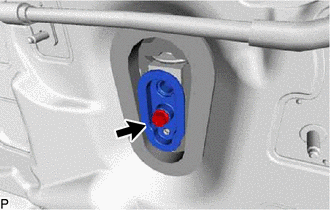
Remove the bolt and rotate the hook connector as shown in the illustration.
-
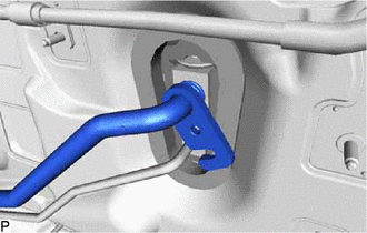
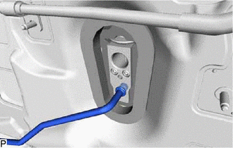
Disconnect the suction pipe sub-assembly.
-
Remove the O-ring from the suction pipe sub-assembly.
Note
Seal the openings of the disconnected parts using vinyl tape to prevent entry of moisture and foreign matter.
-
-
-
DISCONNECT AIR CONDITIONER TUBE ASSEMBLY (w/ Cooler System)
-
w/o Sub-cool Accelerator:
-
Disconnect the air conditioner tube assembly.
-
Remove the O-ring from the air conditioner tube assembly.
Note
Seal the openings of the disconnected parts using vinyl tape to prevent entry of moisture and foreign matter.
-
-
-
DISCONNECT AIR CONDITIONER TUBE AND ACCESSORY ASSEMBLY (w/ Cooler System)
-
w/ Sub-cool Accelerator:
-
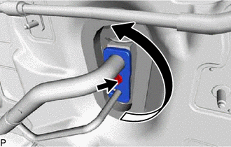
Remove the bolt and rotate the hook connector as shown in the illustration.
-
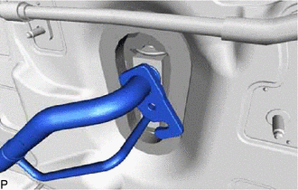
Disconnect the air conditioner tube and accessory assembly.
-
Remove the 2 O-rings from the air conditioner tube and accessory assembly.
Note
Seal the openings of the disconnected parts using vinyl tape to prevent entry of moisture and foreign matter.
-
-
-
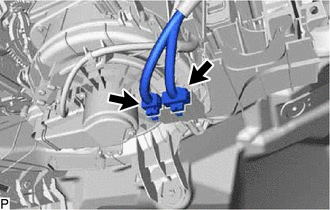
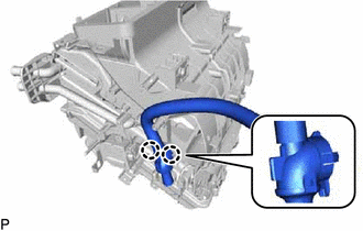
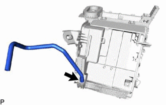
DISCONNECT HEATER WATER OUTLET HOSE A
-
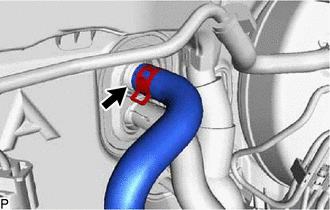
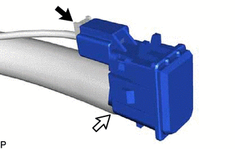
Using pliers, grip the claws of the clip and slide the clip to disconnect the heater water outlet hose A.
Note
-
Do not apply excessive force to the heater water outlet hose A.
-
Prepare a drain pan or cloth in case the coolant leaks.
-
-
-
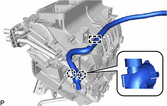
DISCONNECT HEATER WATER INLET HOSE A
-
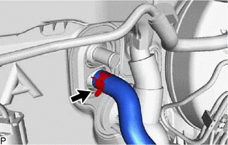
Using pliers, grip the claws of the clip and slide the clip to disconnect the heater water inlet hose A.
Note
-
Do not apply excessive force to the heater water inlet hose A.
-
Prepare a drain pan or cloth in case the coolant leaks.
-
-
-
REMOVE LOWER INSTRUMENT PANEL SUB-ASSEMBLY
for Sedan: Click here
for Hatchback, Wagon: Click here
-
REMOVE STEERING COLUMN ASSEMBLY
-
REMOVE INSTRUMENT PANEL JUNCTION BLOCK ASSEMBLY WITH MAIN BODY ECU (for LHD)
-
REMOVE INSTRUMENT PANEL JUNCTION BLOCK ASSEMBLY WITH MAIN BODY ECU (for RHD)
-
REMOVE DRIVING SUPPORT ECU ASSEMBLY (for 1ND-TV)
w/ Cruise Control System:
-
REMOVE TELEMATICS TRANSCEIVER (w/ Manual (SOS) Switch)
-
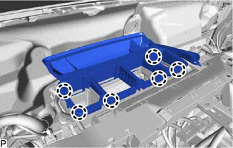
REMOVE REAR NO. 1 AIR DUCT (for Cold Area)
-
Disengage the 8 claws and remove the rear No. 1 air duct.
-
-
REMOVE COOLER (ROOM TEMP. SENSOR) THERMISTOR (for Automatic Air Conditioning System)
-
Disconnect the connector and aspirator to remove the cooler (room temp. sensor) thermistor.
-
-
REMOVE DEFROSTER NOZZLE ASSEMBLY
-
Disengage the 6 claws and remove the defroster nozzle assembly.
-
-
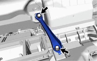
REMOVE CENTER INSTRUMENT PANEL TO COWL BRACE
-
Remove the 2 bolts and center instrument panel to cowl brace.
-
-
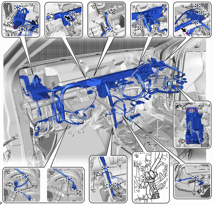
DISCONNECT INSTRUMENT PANEL WIRE (for LHD)
-
for Cold Area:
-
Disconnect the 2 connectors.
-
-
Remove the 2 bolts <A> and disconnect the ground portion of the wiring harness protector cover and earth wire.
*A w/ ECU Integration Box RH *B w/o Radio Receiver *C for Automatic Air Conditioning System *D for Manual Air Conditioning System *a Ground Portion of the Wiring Harness Protector Cover *b Earth Wire *c Guide *d Clamp 
Bolt <A> 
Bolt <B> 
Bolt <C> 
Connector -
Remove the 5 bolts <B>.
-
w/ ECU Integration Box RH:
-
Remove the 3 bolts <C>.
-
Disengage the guide and disconnect the ECU integration box RH.
-
-
Disconnect each connector.
-
Disengage each clamp and disconnect the instrument panel wire.
-
-
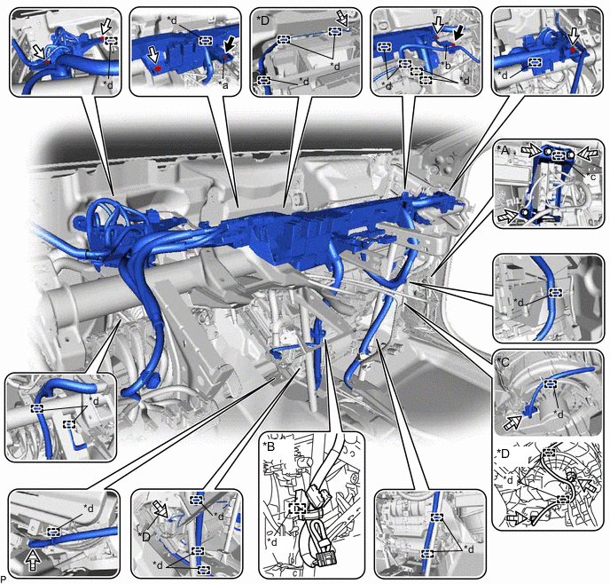
DISCONNECT INSTRUMENT PANEL WIRE (for RHD)
-
for Cold Area:
-
Disconnect the 2 connectors.
-
-
Remove the 2 bolts <A> and disconnect the ground portion of the wiring harness protector cover and earth wire.
*A w/ ECU Integration Box RH *B w/o Radio Receiver *C for Manual Air Conditioning System *D for Automatic Air Conditioning System *a Ground Portion of the Wiring Harness Protector Cover *b Earth Wire *c Guide *d Clamp Bolt <A> Bolt <B> Bolt <C> Connector -
Remove the 4 bolts <B>.
-
w/ ECU Integration Box RH:
-
Remove the 3 bolts <C>.
-
Disengage the guide and disconnect the ECU integration box RH.
-
-
Disconnect each connector.
-
Disengage each clamp and disconnect the instrument panel wire.
-
-
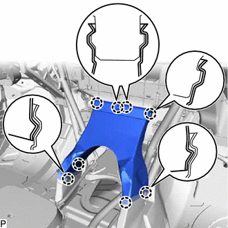
REMOVE NO. 1 INSTRUMENT PANEL BRACE SUB-ASSEMBLY
-
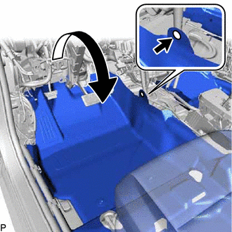
Using a clip remover, remove the clip.
-
Turn back the front floor carpet assembly as shown in the illustration.
-
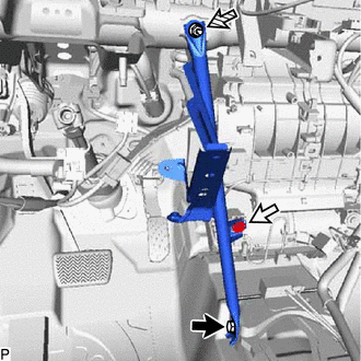
Bolt Screw Nut Remove the bolt, screw, nut and No. 1 instrument panel brace sub-assembly.
-
-
REMOVE NO. 2 INSTRUMENT PANEL BRACE SUB-ASSEMBLY
-
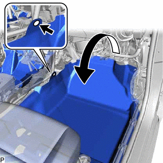
Using a clip remover, remove the clip.
-
Turn back the front floor carpet assembly as shown in the illustration.
-
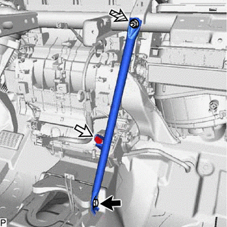
Bolt Screw Nut Remove the bolt, screw, nut and No. 2 instrument panel brace sub-assembly.
-
-
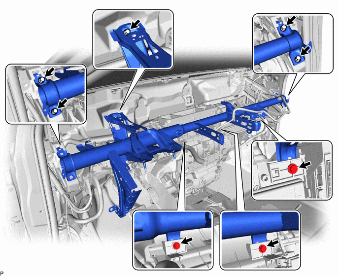
REMOVE INSTRUMENT PANEL REINFORCEMENT ASSEMBLY
-
Remove the 8 bolts and instrument panel reinforcement assembly.
-
-
REMOVE AIR CONDITIONER UNIT ASSEMBLY
-
Disconnect the drain cooler hose.
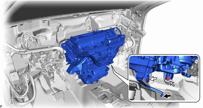
Bolt Nut -
Remove the bolt, nut and air conditioner unit assembly.
-
-
REMOVE NO. 2 AIR DUCT SUB-ASSEMBLY
-
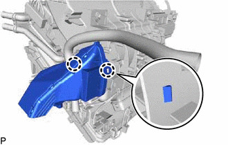
Disengage the 2 claws and remove the No. 2 air duct sub-assembly.
Note
If any of the claws of the No. 2 air duct sub-assembly have been cracked or deformed during removal, make sure to replace the air duct with a new one. Failure to do so may cause the No. 2 air duct sub-assembly to fall off or noise to occur.
-
-
REMOVE NO. 3 AIR DUCT SUB-ASSEMBLY
-
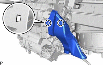
Disengage the 2 claws and remove the No. 3 air duct sub-assembly.
Note
If any of the claws of the No. 3 air duct sub-assembly have been cracked or deformed during removal, make sure to replace the air duct with a new one. Failure to do so may cause the No. 3 air duct sub-assembly to fall off or noise to occur.
-
-
REMOVE AIR CONDITIONING RADIATOR ASSEMBLY
-
for Cold Area:
-
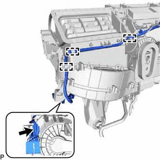
Remove the screw.
-
Disengage each clamp and disconnect the wire harness.
-
-
for Automatic Air Conditioning System:
-
Disconnect the connector.
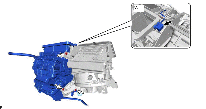
*A for Automatic Air Conditioning System - -
-
-
Remove the 3 screws and air conditioning radiator assembly.
-
-
REMOVE HEATER COVER (except Cold Area)
-
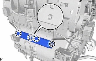
Disengage the 4 claws to remove the heater cover.
-
-
REMOVE ASPIRATOR PIPE (w/o Cooler System)
-
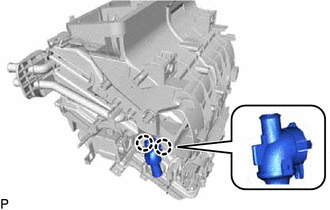
Disengage the 2 claws to remove the aspirator pipe.
-
-
REMOVE ASPIRATOR (for Automatic Air Conditioning System)
-
for LHD:
-
Disengage the 2 claws to remove the aspirator.
-
-
for RHD:
-
Disengage the clamp.
-
Disengage the 2 claws to remove the aspirator.
-
-
-
REMOVE CONSOLE MOUNTING BRACKET LH
-
Remove the screw and console mounting bracket LH.
-
-
REMOVE CONSOLE MOUNTING BRACKET RH
-
Disengage the 2 claws to remove the console mounting bracket RH.
-
-
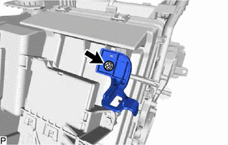
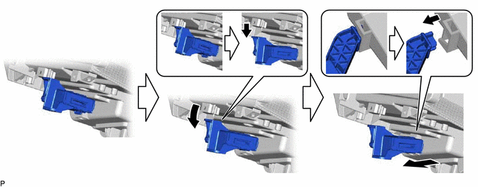
REMOVE AIR CONDITIONING AMPLIFIER ASSEMBLY (for Manual Air Conditioning System)
-
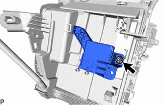
Remove the screw.
-
Remove the air conditioning amplifier assembly as shown in the illustration.
-
-
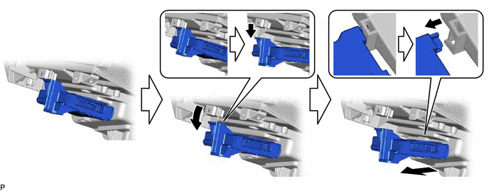
REMOVE AIR CONDITIONING AMPLIFIER ASSEMBLY (for Automatic Air Conditioning System)
-
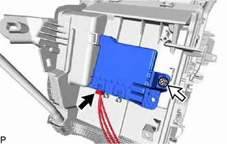
Disconnect the connector.
-
Remove the screw.
-
Remove the air conditioning amplifier assembly as shown in the illustration.
-
-
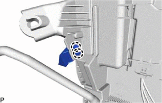
REMOVE DRAIN COOLER HOSE
-
Remove the drain cooler hose.
-
-
REMOVE AIR CONDITIONING HARNESS ASSEMBLY (for Automatic Air Conditioning System)
-
Disengage each clamp.
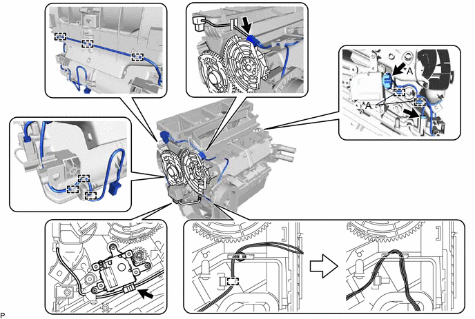
*A for Dual Type - - -
Disconnect each connector.
-
Remove the air conditioning harness assembly as shown in the illustration.
-