COMBUSTION TYPE POWER HEATER SYSTEM Power Heater Fuel Pump Circuit
DESCRIPTION
When the heater switch assembly is turned on, the heater assembly sends a drive signal to the heater pump assembly. The heater assembly then receives the fuel necessary for combustion and starts operating.
WIRING DIAGRAM
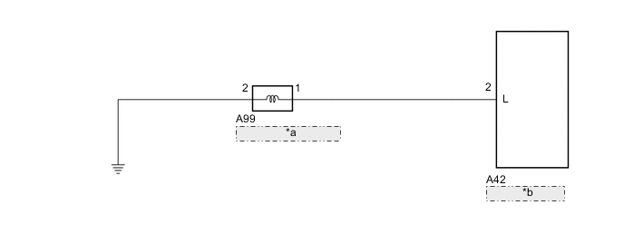
| *a | Heater Pump Assembly |
| *b | Heater Assembly |
PROCEDURE
-
CHECK HARNESS AND CONNECTOR (HEATER ASSEMBLY - HEATER PUMP ASSEMBLY)
-
Disconnect the A42 heater assembly connector.
-
Disconnect the A99 heater pump assembly connector.
-
Measure the resistance according to the value(s) in the table below.
Standard Resistance Tester Connection Condition Specified Condition A42-2 (L) - A99-1 Always Below 1 Ω A42-2 (L) - Body ground Always 10 kΩ or higher Result Proceed to OK NG
NG 
REPAIR OR REPLACE HARNESS OR CONNECTOR
OK 
-
-
CHECK HARNESS AND CONNECTOR (HEATER PUMP ASSEMBLY - BODY GROUND)
-
Measure the resistance according to the value(s) in the table below.
Standard Resistance Tester Connection Condition Specified Condition A99-2 - Body ground Always Below 1 Ω Result Proceed to OK NG
NG
REPAIR OR REPLACE HARNESS OR CONNECTOR
OK
-
-
INSPECT HEATER PUMP ASSEMBLY
-
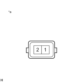
*a Component without harness connected
(Heater Pump Assembly)
Measure the resistance according to the value(s) in the table below.
Standard Resistance Tester Connection Condition Specified Condition 1 - 2 Always 9 to 12 Ω -
Inspect heater pump assembly operation.
-
Connect a positive (+) lead from the battery to terminal 1 and a negative (-) lead to terminal 2, and check the pressure of the hose by hand.
Note
This inspection must be done quickly (within 10 seconds) to prevent damage to the heater pump assembly.
OK Pressure is applied to the hose.
Result Proceed to OK NG -
NG
REPLACE HEATER PUMP ASSEMBLY Click here
OK
-
-
INSPECT HEATER ASSEMBLY
-
Reconnect the A42 heater assembly connector.
-
Measure the voltage according to the value(s) in the table below.
Standard Voltage Tester Connection Condition Specified Condition A99-1 - Body ground Engine running
Heater switch assembly: On
11 to 14 V A99-1 - Body ground Engine running
Heater switch assembly: Off
Below 1 V Result Proceed to OK NG
OK
PROCEED TO NEXT SUSPECTED AREA SHOWN IN PROBLEM SYMPTOMS TABLE Click here
NG
REPLACE HEATER ASSEMBLY Click here
-