AIR CONDITIONING UNIT REASSEMBLY
PROCEDURE
-
INSTALL NO. 1 COOLER THERMISTOR
-
INSTALL NO. 1 COOLER EVAPORATOR SUB-ASSEMBLY
-
Sufficiently apply compressor oil to 2 new O-rings and the fitting surfaces of the No. 1 cooler evaporator sub-assembly.
Compressor Oil ND-OIL 8 or equivalent -
Install the 2 O-rings to the No. 1 cooler evaporator sub-assembly.
Note
Keep the O-rings and O-ring fitting surfaces free of foreign matter.
-
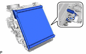
Install the No. 1 cooler evaporator sub-assembly with the front evaporator temperature sensor (No. 1 cooler thermistor) to the upper heater case.
-
Engage the clamp.
-
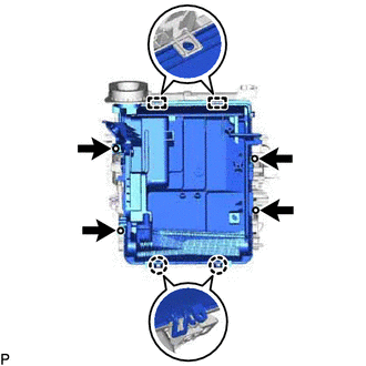
Engage the 2 guides and 2 claws to install the lower heater case.
-
Install the 4 screws.
-
-
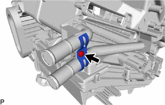
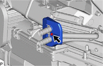
INSTALL COOLER EXPANSION VALVE
-
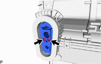
Using a 4 mm hexagon socket wrench, install the cooler expansion valve with the 2 hexagon bolts.
- Torque:
- 3.5 N*m { 36 kgf*cm, 31 in.*lbf }
-
-
INSTALL HEATER RADIATOR UNIT SUB-ASSEMBLY (for Sedan)
-
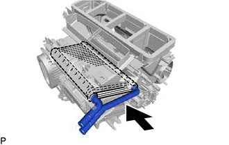
Install the heater radiator unit sub-assembly to the air conditioning radiator assembly as shown in the illustration.
-
Install the clamp with the screw.
-
-
INSTALL HEATER RADIATOR UNIT SUB-ASSEMBLY (for Hatchback, Wagon)
-
Install the heater radiator unit sub-assembly to the air conditioning radiator assembly as shown in the illustration.
-
-
INSTALL HEATER COVER BRACKET (for Hatchback, Wagon)
-
Install the heater cover bracket with the screw.
-
-
INSTALL AIR MIX DAMPER CONTROL CABLE SUB-ASSEMBLY (for Manual Air Conditioning System)
-
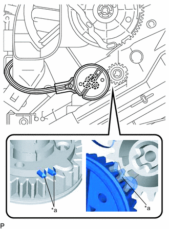
*a Reference Point Using the reference points, engage the 3 claws to install the air mix damper control cable sub-assembly.
-
-
INSTALL NO. 2 HEATER CONTROL CABLE SUB-ASSEMBLY (for Manual Air Conditioning System)
-
*a Reference Point Using the reference points, engage the 3 claws to install the No. 2 heater control cable sub-assembly.
-
Engage the 2 clamps.
-
-
INSTALL NO. 2 AIR MIX DAMPER SERVO SUB-ASSEMBLY (for Automatic Air Conditioning System)
-
for Dual Type:
-
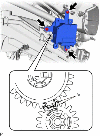
*a Reference Point Using the reference points, install the No. 2 air mix damper servo sub-assembly with the 3 screws.
-
-
-
INSTALL AIR MIX DAMPER SERVO SUB-ASSEMBLY (for Automatic Air Conditioning System)
-
for Single Type:
-
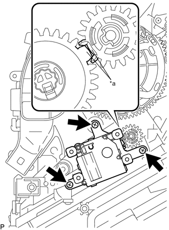
*a Reference Point Using the reference points, install the air mix damper servo sub-assembly with the 2 screws.
-
-
for Dual Type:
-
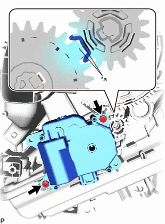
*a Reference Point Using the reference points, install the air mix damper servo sub-assembly with the 3 screws.
-
-
-
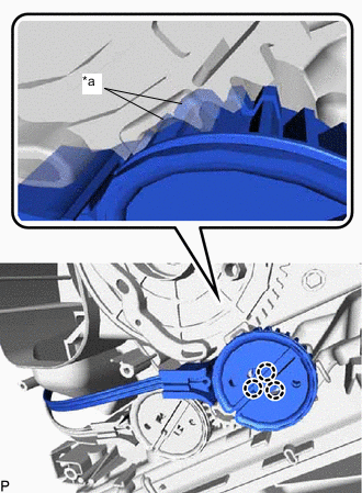
INSTALL MODE DAMPER SERVO SUB-ASSEMBLY (for Automatic Air Conditioning System)
-
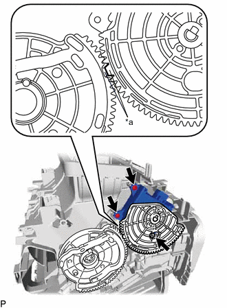
*a Reference Point Using the reference points, install the mode damper servo sub-assembly with the 3 screws.
-
-
INSTALL QUICK HEATER ASSEMBLY (for Cold Area)