AIR CONDITIONING SYSTEM(for Manual Air Conditioning System) PTC Heater Circuit
DESCRIPTION
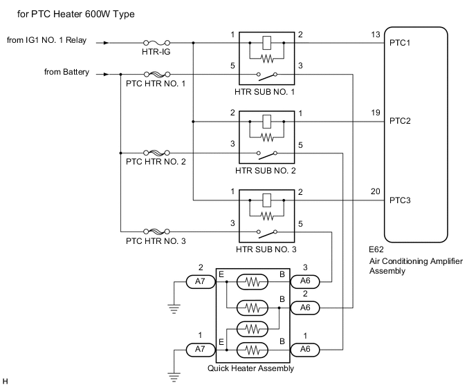
The air conditioning amplifier assembly sends operation signals to the PTC heater relays when the quick heater assembly operation conditions are met. Based on the signals from the air conditioning amplifier assembly, the PTC heater relays turn on, and power is supplied to the quick heater assembly installed in the air conditioning radiator assembly.
| Control ECU | Condition |
|---|---|
| Air Conditioning Amplifier Assembly | Engine running |
| Blower switch: On | |
| Temperature settings: MAX HOT | |
| Light control switch assembly off | |
|
|
| Ambient temperature: 10°C or lower |
WIRING DIAGRAM

CAUTION / NOTICE / HINT
Note
Inspect the fuses for circuits related to this system before performing the following procedure.
PROCEDURE
-
PERFORM ACTIVE TEST USING GTS
-
Connect the GTS to the DLC3.
-
Turn the ignition switch to ON.
-
Turn the GTS on.
-
Enter the following menus: Body Electrical / Air Conditioner / Active Test.
-
Check the operation by referring to the table below.
Body Electrical > Air Conditioner > Active TestTester Display Measurement Item Control Range Diagnostic Note Heater Active Level Quick heater assembly Min.: 0, Max.: 3 -
Body Electrical > Air Conditioner > Active TestTester Display Heater Active Level OK Heater Active Level changes normally. Result Proceed to OK NG
NG 
PROCEED TO NEXT SUSPECTED AREA SHOWN IN PROBLEM SYMPTOMS TABLE Click here
OK 
-
-
INSPECT PTC HEATER RELAY
-
for PTC heater 600W type.
-
Remove the PTC heater relays.
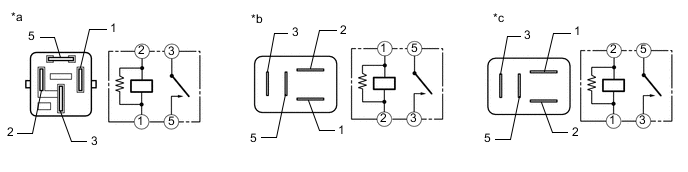
*a Component without harness connected
(HTR SUB NO. 1 Relay)
*b Component without harness connected
(HTR SUB NO. 2 Relay)
*c Component without harness connected
(HTR SUB NO. 3 Relay)
-
Measure the resistance according to the value(s) in the table below.
Standard Resistance Tester Connection Condition Specified Condition 3 - 5 Battery voltage is not applied between terminals 1 and 2 10 kΩ or higher 3 - 5 Battery voltage is applied between terminals 1 and 2 Below 1 Ω
-
-
for PTC heater 495W type.
-
Remove the PTC heater relays.
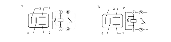
*a Component without harness connected
(HTR SUB NO. 1 Relay and HTR SUB NO. 2 Relay)
*b Component without harness connected
(HTR SUB NO. 3 Relay)
-
Measure the resistance according to the value(s) in the table below.
Standard Resistance Tester Connection Condition Specified Condition 3 - 5 Battery voltage is not applied between terminals 1 and 2 10 kΩ or higher 3 - 5 Battery voltage is applied between terminals 1 and 2 Below 1 Ω
Result Proceed to OK NG -
NG
REPLACE PTC HEATER RELAY
OK
-
-
CHECK HARNESS AND CONNECTOR (PTC HEATER RELAY - POWER SOURCE)
-
Measure the voltage according to the value(s) in the table below.
Standard Voltage HTR SUB NO. 1 Tester Connection Condition Specified Condition Relay terminal 5 - Body ground*1 Always 11 to 14 V Relay terminal 3 - Body ground*2 Always 11 to 14 V Relay terminal 1 - Body ground*1 Ignition switch off Below 1 V Relay terminal 1 - Body ground*1 Ignition switch ON 11 to 14 V Relay terminal 2 - Body ground*2 Ignition switch off Below 1 V Relay terminal 2 - Body ground*2 Ignition switch ON 11 to 14 V Standard Voltage HTR SUB NO. 2 Tester Connection Condition Specified Condition Relay terminal 3 - Body ground Always 11 to 14 V Relay terminal 2 - Body ground Ignition switch off Below 1 V Relay terminal 2 - Body ground Ignition switch ON 11 to 14 V Standard Voltage HTR SUB NO. 3 Tester Connection Condition Specified Condition Relay terminal 3 - Body ground Always 11 to 14 V Relay terminal 1 - Body ground Ignition switch off Below 1 V Relay terminal 1 - Body ground Ignition switch ON 11 to 14 V
-
*1: for PTC Heater 600W Type
-
*2: for PTC Heater 495W Type
Result Proceed to OK NG -
NG
REPAIR OR REPLACE HARNESS OR CONNECTOR
OK
-
-
CHECK HARNESS AND CONNECTOR (PTC HEATER RELAY - AIR CONDITIONING AMPLIFIER ASSEMBLY)
-
Disconnect the E62 air conditioning amplifier assembly connector.
-
Measure the resistance according to the value(s) in the table below.
Standard Resistance HTR SUB NO. 1 Tester Connection Condition Specified Condition Relay terminal 2 - E62-13 (PTC1)*1 Always Below 1 Ω Relay terminal 1 - E62-13 (PTC1)*2 Always Below 1 Ω E62-13 (PTC1) - Body ground Always 10 kΩ or higher Standard Resistance HTR SUB NO. 2 Tester Connection Condition Specified Condition Relay terminal 1 - E62-19 (PTC2) Always Below 1 Ω E62-19 (PTC2) - Body ground Always 10 kΩ or higher Standard Resistance HTR SUB NO. 3 Tester Connection Condition Specified Condition Relay terminal 2 - E62-20 (PTC3) Always Below 1 Ω E62-20 (PTC3) - Body ground Always 10 kΩ or higher
-
*1: for PTC Heater 600W Type
-
*2: for PTC Heater 495W Type
Result Proceed to OK NG -
NG
REPAIR OR REPLACE HARNESS OR CONNECTOR
OK
-
-
CHECK HARNESS AND CONNECTOR (PTC HEATER RELAY - QUICK HEATER ASSEMBLY)
-
Disconnect the A6 quick heater assembly connector.
-
Measure the resistance according to the value(s) in the table below.
Standard Resistance HTR SUB NO. 1 Tester Connection Condition Specified Condition Relay terminal 3 - A6-2 (B)*1 Always Below 1 Ω A6-2 (B) - Body ground*1 Always 10 kΩ or higher Relay terminal 5 - A6-1 (B)*2 Always Below 1 Ω A6-1 (B) - Body ground*2 Always 10 kΩ or higher Standard Resistance HTR SUB NO. 2 Tester Connection Condition Specified Condition Relay terminal 5 - A6-1 (B)*1 Always Below 1 Ω A6-1 (B) - Body ground*1 Always 10 kΩ or higher Relay terminal 5 - A6-2 (B)*2 Always Below 1 Ω A6-2 (B) - Body ground*2 Always 10 kΩ or higher Standard Resistance HTR SUB NO. 3 Tester Connection Condition Specified Condition Relay terminal 5 - A6-3 (B) Always Below 1 Ω A6-3 (B) - Body ground Always 10 kΩ or higher
-
*1: for PTC Heater 600W Type
-
*2: for PTC Heater 495W Type
Result Proceed to OK NG -
NG
REPAIR OR REPLACE HARNESS OR CONNECTOR
OK
-
-
CHECK HARNESS AND CONNECTOR (QUICK HEATER ASSEMBLY - BODY GROUND)
-
Disconnect the A7 quick heater assembly connector.
-
Measure the resistance according to the value(s) in the table below.
Standard Resistance Tester Connection Condition Specified Condition A7-1 (E) - Body ground Always Below 1 Ω A7-2 (E) - Body ground Always Below 1 Ω Result Proceed to OK NG
NG
REPAIR OR REPLACE HARNESS OR CONNECTOR
OK
-
-
INSPECT QUICK HEATER ASSEMBLY
-
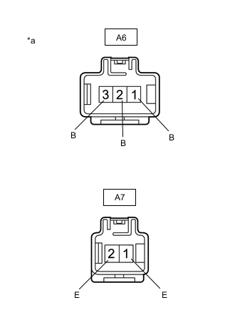
*a Component without harness connected
(Quick Heater Assembly)
Measure the resistance according to the value(s) in the table below.
Standard Resistance Tester Connection Condition Specified Condition A6-1 (B) - A7-1 (E) Always Below 1 Ω A6-2 (B) - A7-1 (E) Always Below 1 Ω A6-2 (B) - A7-2 (E) Always Below 1 Ω A6-3 (B) - A7-2 (E) Always Below 1 Ω Result Proceed to OK NG
OK
REPLACE AIR CONDITIONING AMPLIFIER ASSEMBLY Click here
NG
REPLACE QUICK HEATER ASSEMBLY Click here
-