AIR CONDITIONING SYSTEM(for Manual Air Conditioning System) Heater Control Switch Circuit
DESCRIPTION
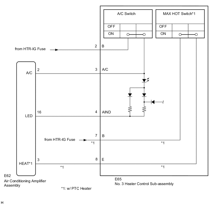
The No. 3 heater control sub-assembly is powered through the HTR-IG fuse. The No. 3 heater control sub-assembly transmits operational signals of each switch to the air conditioning amplifier assembly.
WIRING DIAGRAM
CAUTION / NOTICE / HINT
Note
Inspect the fuses for circuits related to this system before performing the following procedure.
PROCEDURE
-
INSPECT NO. 3 HEATER CONTROL SUB-ASSEMBLY
-
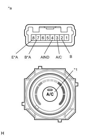
*A w/ PTC Heater *a Component without harness connected
(No. 3 Heater Control Sub-assembly)
*b A/C Switch Measure the resistance.
-
Remove the No. 3 heater control sub-assembly.
-
Measure the resistance according to the value(s) in the table below.
Standard Resistance Tester Connection Condition Specified Condition 2 (B) - 3 (A/C) A/C switch: On Below 1 Ω 2 (B) - 3 (A/C) A/C switch: Off 10 kΩ or higher 7 (B) - 8 (E)*1 MAX HOT switch: On Below 1 Ω 7 (B) - 8 (E)*1 MAX HOT switch: Off 10 kΩ or higher
-
*1: w/ PTC heater
-
-
-
Check the indicator light.
-
Turn the A/C switch on.
-
Connect a positive (+) lead from the battery to terminal 2 (B) and a negative (-) lead to terminal 4 (AIND), and check that the indicator light comes on.
OK The indicator light comes on.
Result Proceed to OK NG -
NG 
REPLACE NO. 3 HEATER CONTROL SUB-ASSEMBLY Click here
OK 
-
-
CHECK HARNESS AND CONNECTOR (NO. 3 HEATER CONTROL SUB-ASSEMBLY - IG POWER SOURCE)
-
Measure the voltage according to the value(s) in the table below.
Standard Voltage Tester Connection Condition Specified Condition E65-2 (B) - Body ground Ignition switch ON 11 to 14 V E65-2 (B) - Body ground Ignition switch off Below 1 V E65-7 (B) - Body ground*1 Ignition switch ON 11 to 14 V E65-7 (B) - Body ground*1 Ignition switch off Below 1 V
-
*1: w/ PTC heater
Result Proceed to OK NG -
NG
REPAIR OR REPLACE HARNESS OR CONNECTOR
OK
-
-
CHECK HARNESS AND CONNECTOR (NO. 3 HEATER CONTROL SUB-ASSEMBLY - AIR CONDITIONING AMPLIFIER ASSEMBLY)
-
Disconnect the E62 air conditioning amplifier assembly connector.
-
Measure the resistance according to the value(s) in the table below.
Standard Resistance Tester Connection Condition Specified Condition E65-3 (A/C) - E62-2 (A/C) Always Below 1 Ω E65-4 (AIND) - E62-16 (LED) Always Below 1 Ω E65-8 (E) - E62-3 (HEAT)*1 Always Below 1 Ω E65-3 (A/C) - Body ground Always 10 kΩ or higher E65-4 (AIND) - Body ground Always 10 kΩ or higher E65-8 (E) - Body ground*1 Always 10 kΩ or higher
-
*1: w/ PTC heater
Result Proceed to OK NG -
OK
PROCEED TO NEXT SUSPECTED AREA SHOWN IN PROBLEM SYMPTOMS TABLE Click here
NG
REPAIR OR REPLACE HARNESS OR CONNECTOR
-