AIR CONDITIONING SYSTEM(for Automatic Air Conditioning System) SYSTEM DESCRIPTION
-
GENERAL
-
The air conditioning system has the following controls.
Control Outline Neural Network Control This control is capable of performing complex control by artificially simulating the information processing method of the nervous system of living organisms in order to establish a complex input/output relationship similar to that of a human brain. Outlet Air Temperature Control Based on the temperature set by the temperature control dial, neural network control calculates outlet air temperature based on input signals from various sensors. Dual Control*1 The temperature settings for the driver and front passenger are controlled independently in order to provide separate vehicle interior temperatures for the right and left sides of the vehicle. Thus, air conditioning that accommodates the occupants' preferences has been realized. Blower Control Controls the blower motor in accordance with the airflow volume that has been calculated by neural network control based on input signals from various sensors. Air Outlet Control Automatically switches the air outlets in accordance with the outlet mode that has been calculated by neural network control. In accordance with the engine coolant temperature, ambient air temperature, amount of sunlight, required blower, outlet temperature and vehicle speed conditions, this control automatically switches the blower outlet to foot/defroster mode to prevent the windows from becoming fogged up when the ambient air temperature is low. Air Inlet Control Automatically controls the air inlet control damper to help achieve the calculated outlet air temperature that is required. Drives the air inlet control servo motor according to the operation of the air inlet control switch and moves the dampers to the fresh or recirculation position. Compressor Control Through the calculation of the target evaporator temperature based on various sensor signals, the air conditioning amplifier optimally controls discharge capacity by regulating the opening extent of the compressor solenoid valve. Defroster Control Defroster control logic is used to improve defroster performance. Rear Defogger Control Refer to Rear Defogger System.
Blower Customize During automatic air conditioning operation, the air volume can be adjusted in 3 levels using the FAST SOFT switch: MEDIUM → SOFT (small air volume) → FAST (large air volume). Diagnosis A Diagnostic Trouble Code (DTC) is stored in memory when the air conditioning amplifier assembly detects a problem with the air conditioning system.
-
*1: for Dual Type
-
-
-
NEURAL NETWORK CONTROL
-
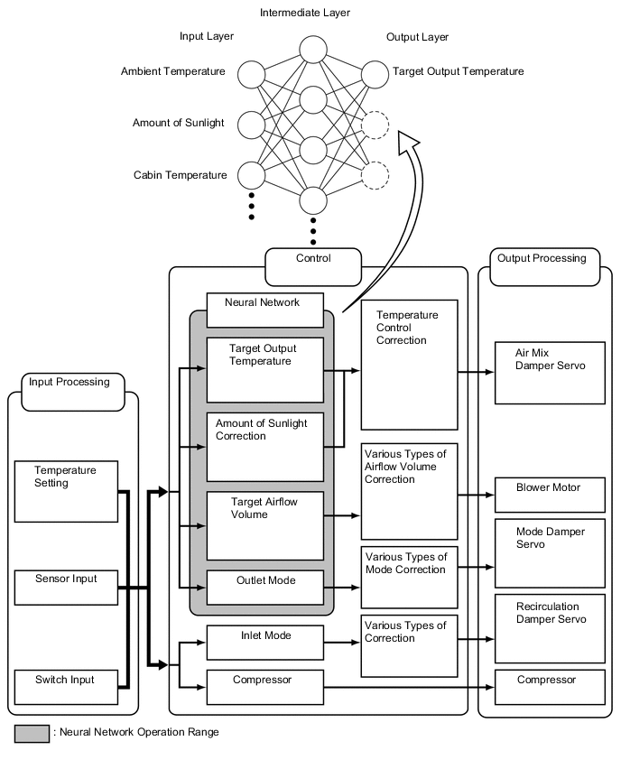
In previous automatic air conditioning systems, the air conditioning amplifier assembly determined the required outlet air temperature and blower air volume in accordance with the calculation formula that has been obtained based on information received from the sensors.
However, because the senses of a person are rather complex, a given temperature is sensed differently, depending on the environment in which the person is situated. For example, a given amount of solar radiation can feel comfortably warm in a cold climate, or extremely uncomfortable in a hot climate. Therefore, as a technique for effecting a higher level of control, a neural network has been adopted in the automatic air conditioning system. With this technique, the data that has been collected under varying environmental conditions is stored in the air conditioning amplifier assembly. The air conditioning amplifier assembly can then effect control to provide enhanced air conditioning comfort.
-
The neural network control consists of neurons in the input layer, intermediate layer and output layer. The input layer neurons process the input data of the outside temperature, the amount of sunlight and the room temperature based on the outputs of the switches and sensors, and output them to the intermediate layer neurons. Based on this data, the intermediate layer neurons adjust the strength of the links among the neurons. The sum of these is then calculated by the output layer neurons in the form of the required outlet temperature, solar correction, target airflow volume and outlet mode control volume. Accordingly, the air conditioning amplifier assembly controls the servo motors and blower motor in accordance with the control volumes that have been calculated by the neural network control.
-
-
MODE POSITION AND DAMPER OPERATION
-
Mode Position and Damper Operation.
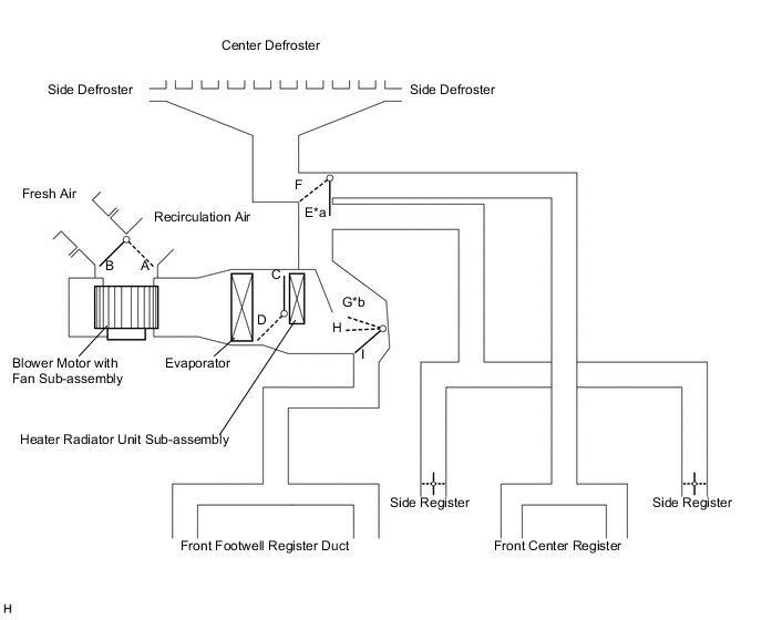
Text in Illustration *a Air also blows out of the side registers *b Air also blows out of the side registers and defrosters Functions of Main Dampers Control Damper Operation Position Damper Position Operation Air Inlet Control Damper FRESH A Allows fresh air to enter. RECIRCULATION B Causes internal air to recirculate. Air Mix Control Damper MAX COLD to MAX HOT Temperature Setting C - D Varies the mixture ratio of warm air and cool air in order to regulate the temperature continuously between hot and cold. Air Outlet Control Damper DEF

E, I Air blows out of the center defroster, side defrosters and side registers. FOOT / DEF

E, H Air blows out of the front footwell register ducts, side registers and center defroster. FOOT

E, G Air blows out of the side registers, front footwell register ducts. In addition, air blows out slightly from the center defroster and side defrosters. BI-LEVEL

F, H Air blows out of the front footwell register ducts, front center registers and side registers. FACE

F, I Air blows out of the front center registers and side registers.
-
-
AIR OUTLETS AND AIRFLOW VOLUME
-
Air Outlets and Airflow Volume.
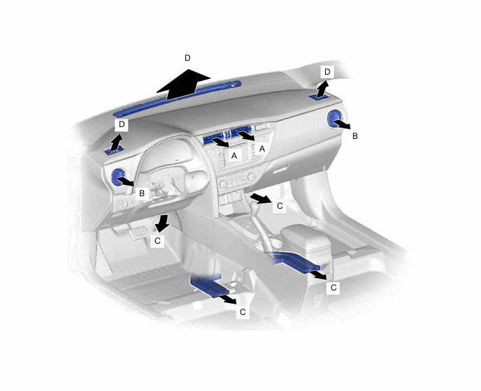
Indication Mode FACE FOOT DEF CTR SIDE C D A B FACE 

B/L 
FOOT 
F/D DEF The size of each circle ○ indicates the ratio of airflow volume.
-
-
COMPRESSOR
-
General
-
The compressor assembly with pulley is a continuously variable capacity type with a capacity that varies in accordance with the cooling load of the air conditioning.
-
The compressor assembly with pulley consists of the shaft, lug plate, piston, shoe, crank chamber, cylinder and solenoid control valve.
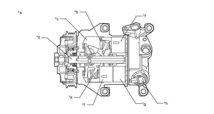
*a Example *b Shoe *c Crank Chamber *d Shaft *e Lug Plate *f Piston *g Cylinder *h Solenoid Control Valve -
A variable suction side throttle is used.
-
Refrigerant inlet pressure is applied to the top of the variable suction side throttle and crank chamber pressure is applied to the bottom of the variable suction side throttle.
-
The pressure difference moves the variable suction side throttle up and down, expanding and contracting the refrigerant inlet passage.
-
When the refrigerant flow is at a maximum, the refrigerant inlet pressure is greater than the crank chamber pressure. This causes the variable suction side throttle to move down, fully opening the refrigerant inlet passage and lowering the refrigerant inlet pressure.
-
When the amount of refrigerant flow is controlled, the crank chamber pressure is greater than the refrigerant inlet pressure, raising the variable inlet throttle to contract the flow passage.
-
These controls suppress noise by reducing pulsation from the refrigerant inlet.
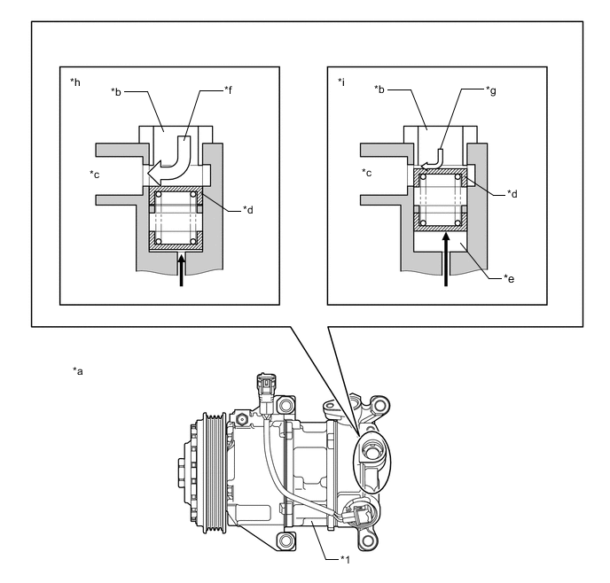
*a Example *b Refrigerant Passage A *c Inlet Chamber *d Variable Suction Side Throttle *e Crank Pressure Inlet Chamber *f High Flow *g Low Flow *h Maximum Volume of Refrigerant *i Controlled Volume of Refrigerant - - *1 Compressor Assembly with Pulley - - 
Crank Chamber Pressure 
Refrigerant Flow -
-
A Damper Limiter (DL) type air conditioning pulley is used. A cylinder-type damper is used for this compressor assembly with pulley and torque fluctuations have been suppressed, thus making an inertia weight unnecessary. As a result, an weight of the compressor assembly with pulley has been reduced.
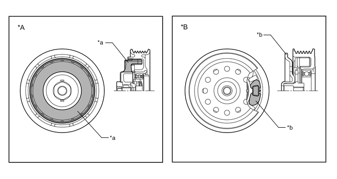
*A Damper Limiter (DL) Type Air Conditioning Pulley *B Conventional Type Air Conditioning Pulley *a Damper *b Inertia Weight
-
-
Operation
-
The crank chamber is connected to the suction passage. A solenoid control valve is provided between the suction passage (low pressure) and the discharge passage (high pressure).
-
The solenoid control valve operates under duty cycle control in accordance with the signals from the air conditioning amplifier assembly.
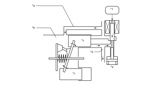
*a Suction Passage *b Crank Chamber *c Piston *d Discharge Passage *e Solenoid Control Valve - - *1 Air Conditioning Amplifier Assembly - - -
When the solenoid control valve closes (the solenoid coil is energized), a difference in pressure is created and the pressure in the crank chamber decreases. Then, the pressure applied to the right side of the piston becomes greater than the pressure applied to the left side of the piston. This compresses the spring and tilts the lug plate. As a result, the piston stroke increases and the discharge capacity increases.
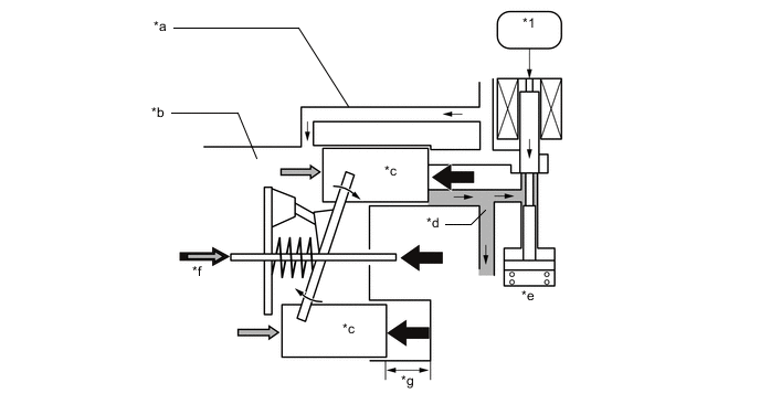
*a Suction Passage *b Crank Chamber *c Piston *d Discharge Passage *e Solenoid Control Valve *f Crank Chamber Pressure + Spring Force *g Piston Stroke: Large - - *1 Air Conditioning Amplifier Assembly - - -
When the solenoid control valve opens (the solenoid coil is not energized), the difference in pressure disappears. Then, the pressure applied to the left side of the piston becomes the same as the pressure applied to the right side of the piston. Thus, the spring elongates and eliminates the tilt of the lug plate. As a result, there is a small piston stroke and the discharge capacity decreases.
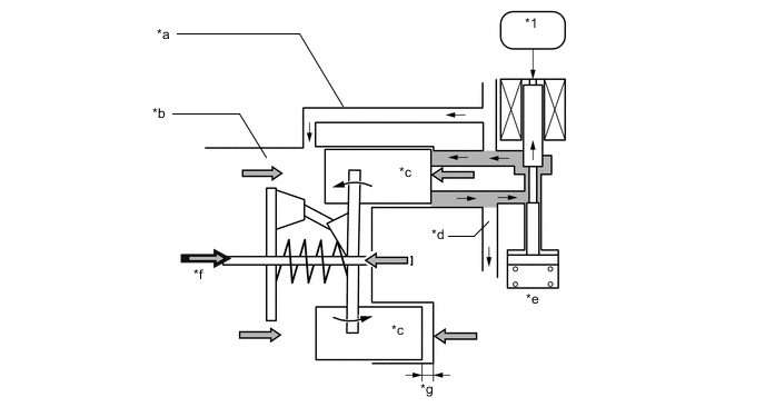
*a Suction Passage *b Crank Chamber *c Piston *d Discharge Passage *e Solenoid Control Valve *f Crank Chamber Pressure + Spring Force *g Piston Stroke: Small - - *1 Air Conditioning Amplifier Assembly - -
-
-
-
NO. 1 COOLER THERMISTOR
The No. 1 cooler thermistor detects the temperature of the cool air immediately after the evaporator in the form of resistance changes, and outputs it to the air conditioning amplifier assembly.
-
BLOWER MOTOR WITH FAN SUB-ASSEMBLY
The blower motor has a built-in blower controller, and is controlled using duty control performed by the air conditioning amplifier assembly.
-
BUS CONNECTOR (AIR CONDITIONING HARNESS ASSEMBLY)
-
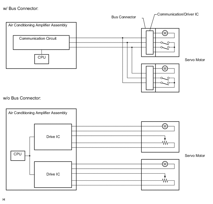
Bus connectors are used in the wire harness that connects the servo motors to the air conditioning amplifier assembly.
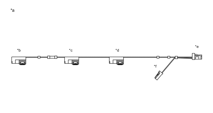
*a Example *b Bus Connector
(to Air Inlet Control Servo Motor Sub-assembly)
*c Bus Connector
(to Air Outlet Control Servo Motor Sub-assembly)
*d Bus Connector
(to Air Mix Control Servo Motor Sub-assembly)
*e to Air Conditioning Amplifier Assembly *f to No. 1 Cooler Thermistor -
Each bus connector has a built-in communication/driver IC which communicates with the air conditioning amplifier assembly, actuates the servo motor, and has a position detection function. This enables bus communication for the servo motor wire harness, for a more lightweight construction and a reduced number of wires.
-
-
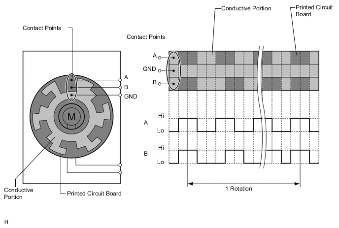
SERVO MOTOR
A pulse pattern type servo motor consists of a printed circuit board and a servo motor. The printed circuit board has three contact points, and can transmit two ON-OFF signals to the air conditioning amplifier assembly based on the difference of the pulse phases. The bus connector can detect the damper position and movement direction with these signals.
-
COOLER (ROOM TEMP. SENSOR) THERMISTOR
The cooler (room temp. sensor) thermistor detects the cabin temperature based on changes in the resistance of its built-in thermistor and sends a signal to the air conditioning amplifier assembly.
-
THERMISTOR ASSEMBLY
The thermistor assembly detects the outside temperature based on changes in the resistance of its built-in thermistor and sends a signal to the air conditioning amplifier assembly.
-
COOLER (SOLAR SENSOR) THERMISTOR
The cooler (solar sensor) thermistor detects (in the form of changes in the current that flows through the built-in photo diode) the changes in the amount of sunlight and outputs these sunlight strength signals to the combination meter assembly.
-
AIR CONDITIONER PRESSURE SENSOR
The air conditioner pressure sensor detects the refrigerant pressure and outputs it to the air conditioning amplifier assembly in the form of voltage changes.